-
E-mail
oubeihaiyang.1688.com
-
Phone
13676799385
-
Address
No. 245 Linxia Road, Zhangbao Industrial Zone, Sanqiao Industrial Park, Wenzhou
Product Categories
Yongjia County Marine Water Pump Factory

AFB single-stage single suction cantilever corrosion-resistant pump
NegotiableUpdate on 03/18
- Model
- Nature of the Manufacturer
- Producers
- Product Category
- Place of Origin
Overview
AFB single-stage single suction cantilever corrosion-resistant pump is suitable for media without solid particles, with medium temperature ranging from 0 ℃ to 120 ℃ and inlet pressure not exceeding 2kg/cm2. The AFB single-stage single suction cantilever corrosion-resistant pump is an improved design based on the F-type corrosion-resistant pump, which adopts a new type of impeller driven shaft seal device and belongs to the single-stage single suction cantilever corrosion-resistant centrifugal pump.
Product Details
Model Meaning

Product Introduction
AFB single-stage single suction cantilever corrosion-resistant pump is suitable for media without solid particles, with medium temperature ranging from 0 ℃ to 120 ℃ and inlet pressure not exceeding 2kg/cm2.
The AFB single-stage single suction cantilever corrosion-resistant pump is an improved design based on the F-type corrosion-resistant pump, which adopts a new type of impeller driven shaft seal device and belongs to the single-stage single suction cantilever corrosion-resistant pump.
The overcurrent parts of the AFB single-stage single suction cantilever corrosion-resistant pump in contact with the conveying medium are all made of 1Cr18Ni9Ti material. Used for conveying corrosive liquids without solid particles, with a temperature range of -20 ℃ to+130 ℃ for the conveyed medium. The inlet pressure of the pump shall not exceed 2kg/cm2.
AFB single-stage single suction cantilever corrosion-resistant pumps are widely used in chemical, petroleum, metallurgical, light industry, synthetic fiber, environmental protection, food, pharmaceutical and other sectors. This type of product has the advantages of stable and reliable performance, good sealing performance, beautiful appearance, and easy use and maintenance. To improve product quality, reduce running, emitting, dripping, leaking, prevent pollution, and improve the environment, it plays a significant role.
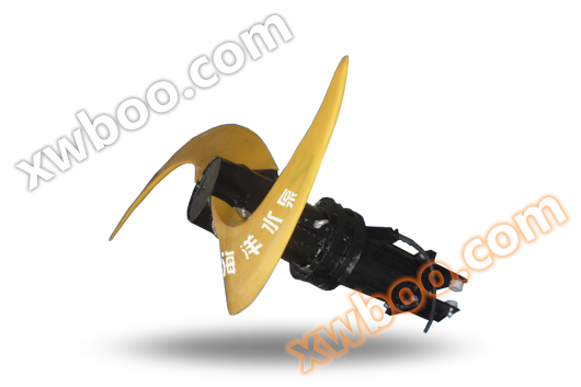
Structural characteristics
The rotation direction of AFB single-stage single suction cantilever corrosion-resistant pump is clockwise when viewed from the suction port towards the motor end.
The AFB single-stage single suction cantilever corrosion-resistant pump and motor are installed on the same base through an elastic coupling.
The shaft seal device of AFB single-stage single suction cantilever corrosion-resistant pump adopts impeller pressure reduction and single or double end mechanical seal structure. The bearing body is filled with J 30 lubricating oil and equipped with an oil cup.
Structure diagram
   
|
Serial Number |
name |
Serial Number |
name |
Serial Number |
name |
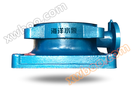
1 |
case of pump |
5 |
pump cover |
9 |
Bearing body |
|
2 |
Sealing ring |
6 |
Sealing cap |
10 |
Pump shaft |
|
3 |
impeller |
7 |
mechanical seal |
11 |
bearing |
|
4 |
IMPELLER NUT |
8 |
Bearing cap |
12 |
coupling |
performance parameter
model |
Inlet and outlet diameter (mm) |
Flow rate (m3/h) |
Head (m) |
Motor power (kw) |
Speed (r/min) |
25FB-16 |
25×25 |
3.6 |
16 |
1.1 |
2900 |
25FB-16A |
25×25 |
3.27 |
12.5 |
0.75 |
2900 |
25FB-25 |
25×25 |
3.6 |
25 |
1.5 |
2900 |
25FB-25A |
25×25 |
3.27 |
20 |
1.1 |
2900 |
25FB-40 |
25×25 |
3.6 |
40 |
3 |
2900 |
25FB-40A |
25×25 |
3.27 |
33.5 |
2.2 |
2900 |
40FB-16 |
40×32 |
7.2 |
16 |
1.5 |
2900 |
40FB-16A |
40×32 |
6.55 |
12 |
1.1 |
2900 |
40FB-20 |
40×32 |
7.2 |
20 |
1.5 |
2900 |
40FB-25 |
40×32 |
7.2 |
25 |
2.2 |
2900 |
40FB-25A |
40×32 |
6.55 |
20.5 |
1.5 |
2900 |
40FB-40 |
40×32 |
7.2 |
40 |
3 |
2900 |
40FB-40A |
40×32 |
6.55 |
32 |
2.2 |
2900 |
40FB-63 |
40×32 |
7.2 |
63 |
7.5 |
2900 |
40FB-63A |
40×32 |
6.72 |
56 |
5.5 |
2900 |
model |
Inlet and outlet diameter (mm) |
Flow rate (m3/h) |
Head (m) |
Motor power (kw) |
Speed (r/min) |
50FB-16 |
50×40 |
14.4 |
16 |
2.2 |
2900 |
50FB-16A |
50×40 |
13.1 |
12 |
1.5 |
2900 |
50FB-25 |
50×40 |
14.4 |
25 |
4 |
2900 |
50FB-25A |
50×40 |
13.1 |
20 |
3 |
2900 |
50FB-40 |
50×40 |
14.4 |
40 |
5.5 |
2900 |
50FB-40A |
50×40 |
13.1 |
32.5 |
5.5 |
2900 |
50FB-63 |
50×40 |
14.4 |
63 |
11 |
2900 |
50FB-63A |
50×40 |
13.1 |
54.5 |
7.5 |
2900 |
65FB-25 |
65×50 |
28.8 |
25 |
5.5 |
2900 |
65FB-25A |
65×50 |
26.2 |
20 |
4 |
2900 |
65FB-30 |
65×50 |
28.8 |
30 |
7.5 |
2900 |
65FB-30A |
65×50 |
26.2 |
25 |
5.5 |
2900 |
65FB-40 |
65×50 |
28.8 |
40 |
11.5 |
2900 |
65FB-40A |
65×50 |
26.2 |
32 |
7.5 |
2900 |
65FB-64 |
65×50 |
28.8 |
64 |
15 |
2900 |
65FB-64A |
65×50 |
26.2 |
55 |
7.5 |
2900 |
model |
Inlet and outlet diameter (mm) |
Flow rate (m3/h) |
Head (m) |
Motor power (kw) |
Speed (r/min) |
80FB-15 |
80×65 |
54.4 |
15 |
5.5 |
2900 |
80FB-15A |
80×65 |
49.1 |
11.5 |
4 |
2900 |
80FB-24 |
80×65 |
54.4 |
24 |
7.5 |
2900 |
80FB-24A |
80×65 |
49.1 |
19 |
7.5 |
2900 |
80FB-38 |
80×65 |
54.4 |
38 |
15 |
2900 |
80FB-38A |
80×65 |
49.1 |
30.5 |
11 |
2900 |
80FB-60 |
80×65 |
54.4 |
60 |
22 |
2900 |
80FB-60A |
80×65 |
49.1 |
52 |
18.5 |
2900 |
100FB-23 |
100×80 |
100.8 |
23 |
15 |
2900 |
100FB-23A |
100×80 |
91.8 |
17.5 |
11 |
2900 |
100FB-37 |
100×80 |
100.8 |
37 |
22 |
2900 |
100FB-37A |
100×80 |
91.8 |
29 |
18.5 |
2900 |
100FB-57 |
100×80 |
100.8 |
57 |
37 |
2900 |
100FB-57A |
100×80 |
91.8 |
52 |
37 |
2900 |
150FB-22 |
150×100 |
190.8 |
22 |
22 |
2900 |
150FB-22A |
150×100 |
173.5 |
17.5 |
18.5 |
2900 |
150FB-35 |
150×100 |
190.8 |
35 |
37 |
2900 |
150FB-35A |
150×100 |
173.5 |
28 |
30 |
2900 |
150FB-56 |
150×100 |
190.8 |
56 |
55 |
2900 |
150FB-56A |
150×100 |
173.5 |
50 |
37 |
2900 |
model |
Inlet and outlet diameter (mm) |
Flow rate (m3/h) |
Head (m) |
Motor power (kw) |
Speed (r/min) |
Performance parameters and selection
1. To meet the needs of energy conservation, it is required that the performance parameters of the pump should strive to meet the actual working conditions. Therefore, the following two methods can be adopted to change the performance curve of the pump.
(1) Change the pump speed: Any pump with a diameter greater than 25mm can be used at a reduced speed, and the lower limit of the head after reduction can reach 3 meters. The principle of reduction is to reduce the speed from 2900 rpm to 1480 rpm, and from 1480 rpm to 9800 rpm. The performance relationship after reduction is Q1=Q (n1/n) H1=H (n1/n) 2. (The value with "l" represents the energy value after deceleration)
(2) Turning the outer diameter of the impeller can change the performance of the pump while keeping the speed constant. The pump performance after turning can be calculated using the following formula: Q '=Q · D'2/D2, H'=H (D'2/D2) 2, N '=N (D'2/D2) 3. The installation dimensions may vary.
2. The basic plane should be calibrated with a spirit level. After the foundation cement solidifies, the pump should be installed on the foundation and the level of the pump and motor shaft should be checked with a spirit level. If it is not level, use shims to adjust until it is level.
3. When the motor, pump, and base are installed separately, the concentricity of the pump shaft and motor should be strictly checked. Inspection method: Use a straightedge to inspect the outer circumference of the pump and motor coupling, and measure the uneven gap with a feeler gauge, which should not exceed 0.1 millimeters. After the two couplings come into contact, maintain a solid gap of 2 millimeters, with an uneven tolerance of 0.3 millimeters within a week. Otherwise, they cannot be concentric, causing vibration, bearing heating, and even damaging pump components.
4. The suction pipeline and pressure outlet of the pump should have their own brackets, and the weight of the pipeline should not be borne by the pump.
5. When the installation position of the pump is higher than the liquid level (note that it is outside the allowable range of the pump suction), a bottom valve should be installed at the end of the suction pipeline. The throat area of the bottom valve should be greater than 50% of the cross-sectional area of the suction pipeline. When the pump is installed below the liquid level, a bottom valve can be omitted, but a control valve and filtering device should be installed on the suction pipeline to prevent debris from being sucked into the pump, causing damage to the impeller and pump components.
6. Before installing the pump, it is necessary to thoroughly clean the debris inside the pipe, such as welding slag, to prevent accidents caused by suction when the pump is started.
Start, stop, and operate
start:
1. Prepare necessary wrenches and tools.
2. Check if the oil level on the bearing body oil gauge is normal.
3. Check whether the rotation direction of the pump is correct. Reverse rotation is strictly prohibited. Incorrect rotation can cause the impeller nut to loosen, allowing corrosive media to enter the shaft neck and cause corrosion, resulting in the pump being unable to work. It may also cause the impeller nut to be thrown out and cause unfortunate accidents. Ensure safe production.
When the installation position of the pump is below the liquid level (backflow situation), the gate valve of the pipeline should be opened before starting the pump to fill the pump with liquid. If the installation position is higher than the liquid level (under vacuum conditions), the pump should be filled and vented before starting to fill the pump and suction pipeline with liquid and exhaust the air inside the pump. 5. After starting the motor, slowly open the discharge gate valve to ensure that the pump is working properly, and then open the valve to the desired level.
stop it:
1. Close the pressure pipeline gate valve.
2. Stop the motor.
3. Close the suction pipeline gate valve.
4. When the ambient temperature is below the freezing point of the liquid, the liquid in the pump should be drained completely.
5. If the pump is not in use for a long time, the corrosive medium inside the pump should be drained and rinsed with clean water. After cleaning, it should be properly stored.
work:
1. The temperature rise of the pump and motor should be checked regularly, mainly the temperature rise of the bearings, and the bearing temperature should not exceed 73 ℃.
2. During operation, if noise or other abnormal sounds are found, the inspection should be stopped immediately and the fault should be eliminated before operation.
3. Pay attention to the sealing device of the fuel cup, maintain oil storage, and replenish and ensure lubrication in a timely manner.
Mechanical seal usage
Usage requirements:
Mechanical seals are used in clean media without suspended particles. Therefore, special attention should be paid to cleaning the pipelines of the new pipeline system.
Installation and disassembly:
1. Before installing the mechanical seal, check all components for damage. If there is any damage, it should be repaired or replaced.
2. Strictly inspect the friction end faces of the moving and stationary rings, and ensure that there are no minor collisions or scratches. Before assembly, apply a layer of clean engine oil to the end faces of the moving and stationary rings.
3. During assembly, attention should be paid to eliminating deviations and adjusting the compression amount of the spring correctly to ensure that it is not too loose or too tight. When tightening screws, they should be tightened evenly to avoid deviation and seal failure.
4. Pay attention to the disassembly sequence of the pump when disassembling.
Fault handling:
1. The pump experienced seal leakage as soon as it started running.
a、 When assembling the mechanical seal, the spring compression is adjusted too loosely.
b、 The dynamic and static ring end faces of the mechanical seal are damaged.
c、 Mechanical seal static ring assembly is skewed.
2. The pump started running normally, but suddenly experienced a serious leak afterwards.
a、 The end face of the dynamic or static ring of the mechanical seal is severely worn.
b、 The mechanical seal fixing screw is loose, causing the spring to lose its function or causing the dynamic ring to tilt.
c、 There are impurities inside the mechanical seal chamber that have trapped the moving ring, preventing it from moving, or between the impurity support and the static ring end, rendering the mechanical seal ineffective.
Fault causes and troubleshooting methods
Fault phenomenon |
reason |
Troubleshooting |
|
Unable to produce liquid
|
1. The pump is not filled with liquid |
1. Recharge the liquid |
2. The suction pipe, discharge pipe, and impeller are blocked by debris |
2. Remove debris |
|
3. There is air in the suction pipe |
3. Repair the pipeline |
|
4. The suction height is too high |
4. Reduce the installation height of the pump |
|
5. The discharge pipe is too thin and the pipeline loss is too large |
5. Replace the pipe with the same diameter as the pump port |
|
6. Require the head to be greater than the pump head |
6. Replace with a new pump |
|
7. Transport heat or volatile media |
7. Reduce inhalation height and backflow |
|
8. Reverse steering |
8. Change direction |
|
|
Insufficient traffic
|
1. The bottom valve is too small |
1. Install a new bottom valve separately |
2. The suction pipeline is not deeply immersed in the liquid enough, and air is brought into the slurry |
2. Increase immersion depth |
|
3. The suction pipeline is too small or blocked by debris |
3. Replace the thick tube and remove debris |
|
4. Severe corrosion of impeller |
4. Replace the impeller with a new one |
|
|
Insufficient head
|
1. Severe corrosion of impeller |
1. Replace the impeller with a new one |
2. The pump performance does not meet the requirements |
2. Replace the pump with a new one |
|
|
Severe pump vibration
|
1. The pump and motor shafts are not concentric |
1. Align the motor and pump axis again |
2. Bending of pump shaft |
2. Remove the straightening or replace the shaft with a new one |
|
Pump bearing overheating |
1. No or insufficient lubricating oil (grease) |
1. Keep going |
2. The motor and pump shaft are not concentric |
2. Adjust the axis |
|
3. Bearing damage |
3. Replace the bearing with a new one |
|
Shaft seal leakage |
1. Excessive import pressure |
1. Reduce import pressure or turn down the inlet gate valve |
motor overheating |
1. Insufficient motor power configuration |
1. Replace the high-power motor with a new one |
Similar Product Recommend