- Phone
-
Address
Oubei and Second Industrial Park, Yongjia County, Zhejiang Province
Product Categories
Yongjia Kaimei Pump Industry Co., Ltd
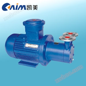
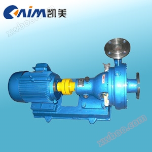
CWB type magnetic driven vortex pump (referred to as magnetic pump)
NegotiableUpdate on 03/27
- Model
- Nature of the Manufacturer
- Producers
- Product Category
- Place of Origin
Overview
Magnetic pumps can be widely used in chemical, pharmaceutical, petroleum, acid, alkali, oil pumping, rare and valuable liquids, venom, volatile liquids, as well as supporting circulating water equipment and filter machines. Especially prone to leakage, flammability, and explosion
Product Details

CWBtypeMagnetic driven vortex pumpProduct Overview
CWBtypeMagnetic driven vortex pump(abbreviated as magnetic force)Vortex pump)It applies the working principle of permanent magnet couplings tocentrifugal pumpThe new product has a reasonable design, advanced technology, full sealing, no leakage, low flow rate, high head, and corrosion resistance. Its performance has reached the advanced level of similar foreign products.
magnetic drive pumpBy replacing dynamic seals with static seals, the overcurrent components of the pump are completely sealed, completely solving the problems of running, emitting, and dripping that other pump mechanical seals cannot avoid.magnetic drive pumpUsing corrosion-resistant and high-strength engineering plastics, corundum ceramics, stainless steel, and other materials as manufacturing materials, it has good corrosion resistance and can protect the transported medium from pollution.
CWBtypeMagnetic driven vortex pumpModel meaning

CWBtypeMagnetic driven vortex pumpProduct Features
1High head, low flow rate, with a specific speed generally less than40;
2Simple structure, small size, and light weight;
3Equipped with a self-lubricating circuit to improve the service life of sliding bearings;’
4Add a cooling circuit to promptly remove magnetic eddy current heat;
5Equipped with an axial clearance adjustment mechanism for the impeller, the clearance can be adjusted at any time to ensure the long-term normal operation of the pump.
6As the viscosity of the conveying medium increases, the efficiency of the pump sharply decreases; Therefore, the viscosity of the medium should not exceed5×10
CWBtypeMagnetic driven vortex pumpstructural diagram

|
1 |
Import and export takeover |
2 |
pump casing |
3 |
gasket |
4 |
Pump cover component |
5 |
impeller |
|
6 |
bearing |
7 |
axis |
8 |
thrust ring |
9 |
Isolation sleeve |
10 |
Internal magnetic components |
|
11 |
External magnetic components |
12 |
Connecting frame |
13 |
baseplate |
14 |
motor |
|
|
CWBtypeMagnetic driven vortex pumpmain purpose
magnetic drive pumpCompact structure, beautiful appearance, small size, low noise, reliable operation, and easy use and maintenance. It can be widely used in chemical, pharmaceutical, petroleum, electroplating, food, film photography and printing, and scientific research institutions. National defense industry and other units pump acid, alkali solution, oil, rare and valuable liquid, venom, volatile liquid, as well as supporting equipment for circulating water and filter machines. Especially for the pumping of liquids that are prone to leakage, flammable, and explosive, this pump is more ideal.
CWBtypeMagnetic driven vortex pumpperformance parameters
|
model |
traffic |
head |
speed |
Motor power |
efficiencythe(%) |
Allow suction height |
impeller diameter |
weight (kg) |
|
CWB20-20 |
0.72 |
20 |
2900 |
0.75 |
22 |
6 |
65 |
26 |
|
CWB20-40 |
0.72 |
40 |
2900 |
1.1 |
18 |
6 |
90 |
32 |
|
CWB20-65 |
0.72 |
65 |
2900 |
2.2 |
15 |
6 |
105 |
36 |
|
CWB25-25 |
1.44 |
25 |
2900 |
1.1 |
26 |
5 |
75 |
28 |
|
CWB25-40 |
1.44 |
40 |
2900 |
1.5 |
24 |
5 |
90 |
40 |
|
CWB25-75 |
1.44 |
75 |
2900 |
4 |
20 |
5 |
110 |
55 |
|
CWB32-30 |
2.88 |
30 |
2900 |
2.2 |
28 |
5 |
90 |
38 |
|
CWB32-50 |
2.88 |
50 |
2900 |
3 |
26 |
5 |
100 |
52 |
|
CWB32-75 |
2.88 |
75 |
2900 |
7.5 |
22 |
5 |
120 |
76 |
|
CWB32-120 |
2.88 |
120 |
2900 |
11 |
18 |
4.5 |
140 |
95 |
|
CWB40-40 |
5.4 |
40 |
2900 |
4 |
30 |
4 |
100 |
70 |
|
CWB40-90 |
5.4 |
90 |
2900 |
11 |
26 |
3.5 |
130 |
105 |
|
CWB50-45 |
9 |
45 |
2900 |
7.5 |
30 |
4 |
110 |
92 |
|
CWB65-50 |
14.4 |
50 |
2900 |
15 |
35 |
3.5 |
120 |
158 |
CWBtypeMagnetic driven vortex pumpinstallation dimensions

|
model |
A |
B |
C |
E |
F |
K |
L |
h |
H |
H1 |
DN |
D |
D1 |
φdl |
φd2 |
|
CWB20-20 |
31 |
210 |
86 |
125 |
92 |
200 |
440 |
80 |
130 |
2J70 |
20 |
90 |
65 |
13.5 |
11 |
|
CWB20-40 |
43 |
210 |
58 |
140 |
102 |
200 |
458 |
80 |
130 |
284 |
20 |
90 |
65 |
13.5 |
11 |
|
CWB20-65 |
48 |
260 |
108 |
140 |
110 |
200 |
486 |
90 |
153 |
313 |
20 |
105 |
75 |
13.5 |
13.5 |
|
CWB25-25 |
45 |
210 |
104 |
140 |
120 |
235 |
462 |
80 |
130 |
330 |
25 |
115 |
85 |
13.5 |
13.5 |
|
CWB25-40 |
49 |
260 |
110 |
140 |
120 |
235 |
488 |
90 |
153 |
353 |
25 |
115 |
85 |
13.5 |
13.5 |
|
CWB25-75 |
25 |
328 |
93 |
190 |
128 |
242 |
606 |
112 |
175 |
386 |
25 |
115 |
85 |
13.5 |
13.5 |
|
CWB32-30 |
52 |
260 |
118 |
140 |
150 |
290 |
522 |
90 |
153 |
368 |
32 |
140 |
100 |
13.5 |
17.5 |
|
CWB32-50 |
28 |
328 |
100 |
160 |
150 |
290 |
614 |
100 |
163 |
378 |
32 |
140 |
100 |
18 |
17.5 |
|
CWB32-75 |
100 |
295 |
169 |
320 |
150 |
356 |
684 |
132 |
212 |
42J7 |
32 |
140 |
100 |
18 |
17.5 |
|
CWB32-120 |
96 |
486 |
173 |
380 |
160 |
416 |
878 |
160 |
240 |
468 |
32 |
140 |
100 |
18 |
17.5 |
|
CWB40-40 |
30 |
328 |
104 |
190 |
160 |
310 |
618 |
112 |
175 |
443 |
40 |
150 |
110 |
13.5 |
17.5 |
|
CWB40-90 |
96 |
486 |
173 |
380 |
160 |
416 |
878 |
160 |
240 |
508 |
40 |
150 |
110 |
18 |
117.5 |
|
CWB50-45 |
104 |
295 |
177 |
320 |
1J70 |
356 |
692 |
132 |
212 |
462 |
50 |
165 |
125 |
18 |
17.5 |
|
CWB65-50 |
82 |
486 |
159 |
380 |
190 |
416 |
878 |
160 |
240 |
520 |
65 |
185 |
145 |
18 |
1J7.5 |
CWBtypeMagnetic driven vortex pumpFaults and troubleshooting methods
|
Fault form |
root cause |
exclusion method |
|
The pump is not producing water |
1.Reverse rotation of water pump 2.Air leakage in the inlet pipeline 3.Insufficient water storage in the pump chamber 4.The voltage is too high, causing the coupling to slip during startup 5.The suction distance is too high |
1.Change the motor wiring 2.Eliminate air leakage 3.Increase storage capacity 4.Adjust the positive voltage 5.Lower the installation position of the pump |
|
Insufficient traffic |
1.The suction pipe diameter is too small 2.Channel blockage 3.Excessive head 4.The speed is too low |
1.Replace the inlet pipe 2.Clean the flow channel 3.Turn up the outlet valve 4.Restore rated speed |
|
Low head |
1.Excessive traffic 2.The speed is too low |
1.Turn down the outlet valve 2.Restore rated speed |
|
The noise is too loud |
1.Severe wear of the shaft 2.Severe wear of the shaft sleeve 3.Drive the magnetic steel cup to contact the isolation sleeve |
1.Replace the pump shaft 2.Replace the shaft sleeve 3.Dismantle the pump head and reassemble it |
|
leakage |
Seal ring damaged |
Replace the sealing ring |
Similar Product Recommend