-
E-mail
842990043@qq.com
-
Phone
13359272398
-
Address
5th Floor, Tongda Building, No. 10 Keji Road, Xi'an City
Product Categories
Xi'an Xinmin Electronic Technology Co., Ltd
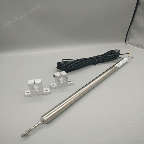


Differential integrated displacement sensor (customizable)
NegotiableUpdate on 02/09
- Model
- Nature of the Manufacturer
- Producers
- Product Category
- Place of Origin
Overview
WYDC differential integrated displacement sensor (customizable) is a sensor that converts linear displacement into analog voltage. Due to its integral structure, it has excellent durability and environmental resistance, with a temperature range of -20 ℃ to 120 ℃.
Product Details
WYDCDifferential integrated displacement sensor (customizable)Working Principle:
Differential transformer is a sensor that converts linear displacement into analog voltage. Due to its integral structure, it has excellent durability and environmental resistance, with a temperature range of -20 ℃~120℃A differential transformer consists of a primary coil, a secondary coil, and a movable iron core. A sine wave excitation with a certain voltage and frequency is applied to the primary coil. The secondary coil generates induced voltage through the movable iron core, and its output characteristicsforThe differential output of two secondary coils is an AC voltage with the same frequency as the excitation signal, which is converted into a DC displacement voltage by the detection circuit and output. The detection circuit consists of rectifying diodes andRCFilter composition, measuring range is the movement stroke of the movable iron core, generally a number+mm~HundredsmmWhen the movable iron core is in the center position, the output voltage is0VGenerate positive and negative voltages proportional to the distance of movement when moving left and right. Its linearity is less than1 %The detection accuracy has reached a certain levelμ mWhen the specified travel distance is exceeded, the error increases.
Purpose and Features:
Differential displacement sensors (customizable) have good environmental adaptability and are widely used to measure various physical quantities that have been pre converted into displacementMeasurement of mechanical quantities that can be converted into displacement changes, such as tension, pressure, vibration, liquid level, etc.sensorofmagnifyThe circuit adopts microelectronics technologyOverallencapsulationIn stainless steelInside the shell. input voltage12VDC~24VDC, output signal±5V、0~5V、0~10Vor0~10mA、04~20mAThe signal can be used in conjunction with a four digit half display.Just use itsensorThe shell is clamped onto the reference object, and the measuring rod is clamped onto the measured point to directly measure the relative displacement between objects.The characteristics are:① No active contacts, high reliability, long lifespan; ② High resolution and good sensitivity; ③ High linearity and good repeatability; ④ Wide measurement range (low resolution when the measurement range is large); ⑤ When there is no input, there is a zero position output voltage, which causes measurement errors; ⑥ The requirement for frequency and amplitude stability of the excitation power supply is high, and it is not suitable for high-frequency dynamic measurement.
Notes:
1Although the circuit adopts internal power protection measures, please check before connecting the power supply. Do not exceed the rated voltage value to avoid affecting the accuracy of measurement and unnecessary losses.
2The installation position of the sensor should not be close to strong magnetic fields. Unless otherwise specified, the sensor should not be used in environments that strongly corrode metals.
3The motion trajectory of the measured point is parallel to the axis of the measuring rod of the sensor. The measurement result is the amount of movement, such as the movement of the sensor probe. The contact surface between the probe and the object being measured should not be uneven.
4The installation and use of sensors should be handled gently to avoid knocking and falling. The fixture should be fixed at both ends of the sensor, and excessive force should be avoided. The housing should not be dented or deformed, which may affect the measurement range. Do not use beyond the range.
5Please power on and preheat the sensor5After minutes, proceed with the formal measurement for use.
6Displacement sensors are precision instruments that have been calibrated and aged before leaving the factory. Users cannot disassemble them at will, otherwise it may affect measurement accuracy and cause sensor damage.
Introduction to the output mode of displacement sensors:
1![]()
![]()
 In the modelWYRepresents a displacement sensor,DC stands for direct current power supply, LRepresenting unidirectional range,DIndicates bidirectional range, and the number represents the range quantity.
Example:WYDCD-100LIndicating: displacement DC power supply, unidirectional100mm range. one hundredLand50DThe measurement range is equal. See figure1.
2. The unidirectional range output is a positive signal (such as 0-5V, 0-10mA, 4-20mA, etc.). The bidirectional range output is positive and negative signals (such as ± 5V, ± 10V, etc.).
3. The range in the size chart is the range to be measured, and within this range, ensure its linearity. When the pull rod exceeds the range, the sensor will enter the nonlinear region. See Figure 2.
4. When the pull rod exceeds the range, if you do not want the voltage to continue to increase, you can limit the output signal. The output after limiting is shown in the figure3.
5. B in the dimension table is the reference value, (B-B minimum) is the sensor's travel, which is the space that the rod can move. The travel is greater than the range. See Figure 2. Separated type is not subject to this limitation.
6. The detachable type allows the rod to be separated from the sensor. In sensors with a range below 30mm, the separated type is easier to achieve no friction between the rod and the sensor. Therefore, it is better to use a separated type for small range high-precision sensors.
7. The output direction of sensors is divided into pull type (i.e. the output increases when the pull rod is pulled outward) and push type (the output increases when the pull rod is pushed inward). Rebound sensors default to push type, while others default to pull type.
8. The rebound sensor is equipped with a spring inside, which pushes the rod outward. There are contacts at the end of the pull rod. Measure by pressing the contact with an external object. Rebound type is only suitable for small range sensors.
Internal structure diagram of WYDC displacement sensor (recommended product):

WYDCThe external dimensions of the sensortechnical indicators:
rule grid |
range (mm) |
A(mm) |
L(mm) |
△L(mm) |
D(mm) |
E(mm) |
||
most small |
most big |
|||||||
5L、2.5D |
5、±2.5 |
130 |
30 |
54 |
15 |
Φ26 |
M5 |
|
10L、5D |
10、±5 |
130 |
30 |
80 |
15 |
Φ26 |
M5 |
|
20L、10D |
20、±10 |
160 |
30 |
95 |
15 |
Φ26 |
M5 |
|
30L、15D |
30、±15 |
180 |
30 |
111 |
15 |
Φ26 |
M5 |
|
50L、25D |
50、±25 |
230 |
30 |
155 |
15 |
Φ26 |
M6 |
|
100L、50D |
100、±50 |
280 |
30 |
205 |
15 |
Φ26 |
M6 |
|
150L、75D |
150、±75 |
380 |
30 |
265 |
15 |
Φ26 |
M6 |
|
200L、100D |
200、±100 |
400 |
30 |
321 |
15 |
Φ26 |
M6 |
|
300L、150D |
300、±150 |
540 |
30 |
485 |
15 |
Φ26 |
M6 |
|
400L、200D |
400、±200 |
670 |
30 |
644 |
15 |
Φ26 |
M6 |
|
500L、250D |
500、±250 |
830 |
50 |
749 |
15 |
Φ26 |
M6 |
|
600L、300D |
600、±300 |
950 |
50 |
749 |
15 |
Φ26 |
M6 |
|
700L、350D |
700、±350 |
960 |
50 |
791 |
20 |
Φ26 |
M6 |
|
800L、400D |
800、±400 |
1093 |
50 |
845 |
20 |
Φ26 |
M8 |
|
900L、450D |
900、±450 |
1242 |
50 |
1004 |
20 |
Φ26 |
M8 |
|
1000L、500D |
1000、±500 |
1336 |
50 |
1088 |
20 |
Φ26 |
M8 |
|
comprehensive accuracy |
0.05%、0.1%、0.5%、1%F·S |
|||||||
output signal |
4-20mA, 0-5V or 0-± 5V, 0-± 10V |
|||||||
power supply voltage |
9V、12V、15V、24VDC(Standard) |
|||||||
Operating Temperature |
-10~60℃ |
|||||||
zero drift |
0.01%/℃ |
|||||||
Sensitivity drift |
0.05%/℃ |
|||||||
Dynamic frequency |
0~200Hz |
|||||||
Note:*LRepresenting one-way,DRepresents bidirectional.* This product has two types: rebound type and separable type.*if neededspecial specificationsSize sensing
Equipment can be customized.

Similar Product Recommend


