-
E-mail
oubeihaiyang.1688.com
-
Phone
13676799385
-
Address
No. 245 Linxia Road, Zhangbao Industrial Zone, Sanqiao Industrial Park, Wenzhou
Product Categories
Yongjia County Marine Water Pump Factory

FSB fluoroplastic alloy chemical corrosion-resistant pump
NegotiableUpdate on 03/18
- Model
- Nature of the Manufacturer
- Producers
- Product Category
- Place of Origin
Overview
Fluoroplastic alloy is an excellent corrosion-resistant material. Our unit uses this material to produce FSB fluoroplastic alloy chemical corrosion-resistant pumps. Strong corrosion-resistant chemical pumps have extremely strong corrosion resistance, high mechanical strength, no aging, no toxin decomposition, and can transport any concentration of acid, alkali solution, oxidant, and other corrosive media. Therefore, they are widely used in industries such as chemical, petroleum, pharmaceutical, pesticide, smelting, dye, papermaking, electroplating, and food.
Product Details
Model Meaning

Product Introduction
Fluoroplastic alloy is an excellent corrosion-resistant material. Our unit uses this material to produce FSB fluoroplastic alloy chemical corrosion-resistant pumps. Strong corrosion-resistant chemical pumps have extremely strong corrosion resistance, high mechanical strength, no aging, no toxin decomposition, and can transport any concentration of acid, alkali solution, oxidant, and other corrosive media. Therefore, they are widely used in industries such as chemical, petroleum, pharmaceutical, pesticide, smelting, dye, papermaking, electroplating, and food.
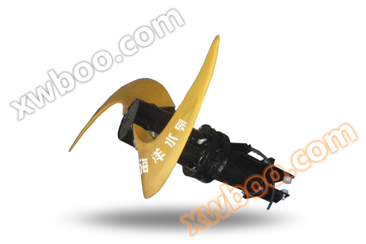
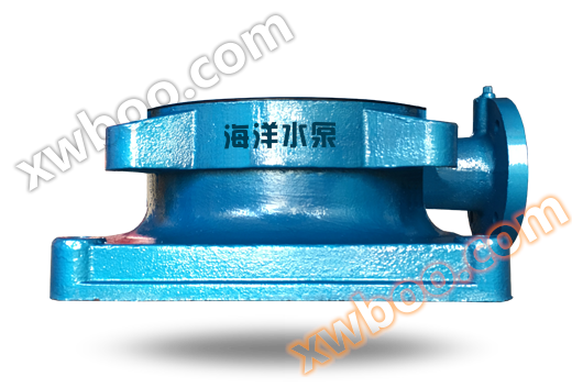
STRUCTURE DESCRIPTION
The FSB fluoroplastic alloy chemical corrosion-resistant pump consists of a chemical pump body, impeller, back cover, seal, bracket, pump shaft, bearing, coupling, suspension bolt, nut, and base plate.
1. Plastic pump body: One steel flange ring is embedded in the connecting parts on both sides, and it is made of molded plastic alloy.
2. The right side of the back cover is embedded with a stainless steel plate (1Cr18Ni9Ti) molded with plastic alloy.
3. Centrifugal pump impeller: The shaft connection method is adopted, and the metal shaft is made of high-quality steel precision machined and wrapped with plastic alloy molded, so that the impeller and the metal shaft are firmly integrated, ensuring that the shaft root and the rear of the impeller bear the torque force during rotation. In this way, the wetted part of the medium is made of plastic alloy.
4. Mechanical seal: Adopting WB 2 type and ST type adjustable end face sealing technology without cooling water, made of materials such as silicon carbide, high-purity alumina ceramics, filled PTFE, graphite, etc.
Structural diagram
 |
Serial Number |
name |
Serial Number |
name |
1 |
pump |
8 |
oiled-paper umbrella |
|
2 |
impeller |
9 |
Oil mirror |
|
3 |
back cover |
10 |
bearing |
|
4 |
cover |
11 |
bearing gland |
|
5 |
Sealing element |
12 |
coupling |
|
6 |
bracket |
13 |
Tighten the bolt |
|
7 |
Pump shaft |
performance parameter
Specification and model |
internet traffic m3/h |
lift m |
caliber |
Equipped with motor KW |
rotational speed r/min |
suction lift m |
efficiency % |
|
Inhalation mm |
Spit out mm |
|||||||
25FSB-10 |
1.5 |
10 |
25 |
20 |
1.5 |
2900 |
6 |
29 |
25FSB-18 |
3.6 |
18 |
25 |
20 |
2.2 |
2900 |
6 |
27 |
40FSB-15 |
5 |
15 |
40 |
32 |
3 |
2900 |
6 |
40 |
40FSB-20 |
10 |
20 |
40 |
32 |
4 |
2900 |
6 |
42 |
40FSB-30 |
10 |
30 |
40 |
32 |
4 |
2900 |
6 |
38 |
40FSB-40 |
10 |
40 |
40 |
32 |
5.5 |
2900 |
5.5 |
35 |
40FSB-50 |
10 |
50 |
40 |
32 |
7.5 |
2900 |
5 |
33 |
50FSB-20 |
15 |
20 |
50 |
40 |
4 |
2900 |
6 |
51 |
50FSB-25 |
15 |
25 |
50 |
40 |
4 |
2900 |
6 |
49 |
50FSB-30 |
15 |
30 |
50 |
40 |
4 |
2900 |
6 |
44.5 |
50FSB-40 |
15 |
40 |
50 |
32 |
5.5-7.5 |
2900 |
5.5 |
35 |
50FSB-50 |
15 |
50 |
50 |
32 |
7.5-11 |
2900 |
5.5 |
33 |
50FSB-63 |
15 |
63 |
50 |
32 |
11 |
2900 |
5.5 |
30 |
65FSB-32 |
29 |
32 |
65 |
50 |
5.5 |
2900 |
6 |
57 |
65FSB-40 |
29 |
40 |
65 |
40 |
11 |
2900 |
5.5 |
53 |
65FSB-50 |
29 |
50 |
65 |
40 |
15 |
2900 |
5.5 |
46 |
65FSB-64 |
29 |
64 |
65 |
50 |
15-18.5 |
2900 |
5.5 |
44 |
80FSB-20 |
50 |
20 |
80 |
65 |
5.5 |
2900 |
6 |
69 |
80FSB-30 |
50 |
30 |
80 |
65 |
7.5 |
2900 |
5.5 |
64 |
80FSB-34 |
50 |
34 |
80 |
65 |
11 |
2900 |
5.5 |
64 |
80FSB-40 |
50 |
40 |
80 |
50 |
11-15 |
2900 |
5.5 |
60 |
80FSB-50 |
50 |
50 |
80 |
50 |
15-18.5 |
2900 |
6 |
53 |
80FSB-55 |
50 |
55 |
80 |
50 |
15-18.5 |
2900 |
5.5 |
47 |
80FSB-80 |
50 |
80 |
80 |
50 |
30-37 |
2900 |
5.5 |
36 |
100FSB-32 |
100 |
32 |
100 |
80 |
18.5-22 |
2900 |
5.5 |
70 |
100FSB-40 |
100 |
40 |
100 |
80 |
18.5-22 |
2900 |
5.5 |
70 |
100FSB-50 |
100 |
50 |
100 |
65 |
22-30 |
2900 |
5.5 |
62 |
precautions
Installation and precautions
Before installation, the FSB fluoroplastic alloy chemical corrosion-resistant pump and motor should be inspected, and all parts should be intact and free of debris inside the pump.
2. Place the pump in a horizontal position, connect the inlet and outlet pipes, and connect the power supply, then manually rotate the coupling Check for any signs of collision or rubbing If the rotation is easy and uniform, the installation is complete.
3. Plastic alloy pumps have lower rigidity than metals, so the weight of the pipeline cannot be directly pressed on the pump body. Additional brackets should be added to support the inlet and outlet pipelines Pumps with high head should also be equipped with check valves at the outlet To prevent water hammer damage caused by sudden shutdown.
4. All joints of FSB fluoroplastic chemical pumps must be kept sealed To prevent air leakage and liquid from affecting the working performance of the pump.
5. If there is any movement or abnormal sound during operation Immediately stop the vehicle to investigate the reason Therefore, work can only be carried out after elimination.
Start and Stop
1. Fill the water pump with sufficient liquid (drainage).
2. Check if the oil level in the bracket oil chamber is within the specified range.
3. Check the direction of motor operation Check the rotation mark of the pump.
4. Close the outlet valve and pressure gauge plug.
5. Start the motor Open the pressure gauge plug Slowly open the outlet valve when the pressure gauge pointer reaches the desired position Stop adjusting the size of the outlet valve.
When making an important stop, first close the water outlet valve and then cut off the power supply.
Disassembly and assembly
disassemble
1. The pump and motor are connected using a claw type coupling. When disassembling, first loosen the four connecting bolts between the bracket and the base Disconnect the pump from the motor.
2. Loosen the connecting bolts of the pump body back cover Gently tap the pump body with a wooden handle to detach it.
3. Loosen the suspension bolts connecting the impeller shaft and pump shaft with a Mohs taper in the coupling.
4. Release the mechanical seal! Without fixing the screws, lightly tap the central suspension bolt of the coupling with a wooden hammer, loosen the Mohs taper of the impeller shaft and pump shaft, and then pull out the impeller, rear cover, and sealing ring Loosen the cover screw on the back cover Remove the static damage.
5. Loosen the left and right cover screws of the pump shaft Remove the pump shaft, bearings, and clean the bracket oil chamber. Assemble the sealing components in the reverse order of disassembly, including the dynamic ring, static ring, rear cover, gland, impeller, pump body, etc., and tighten the bolts.
The use and precautions of mechanical seals
The FSB fluoroplastic alloy chemical corrosion-resistant pump is equipped with mechanical seals of different materials according to different usage conditions. Our factory normally installs the WB2 type seal, which is made of elastic graphite of alumina ceramic and filled with PTFE face. Please pay attention to the following points when using it:
1. Generally, mechanical seals are suitable for clean media without suspended hard particles. If there are particles, please inform us in advance when signing the contract about the newly installed series of pipelines and liquid storage tanks. They should be carefully cleaned to prevent solid impurities from entering the sealing end face and causing the seal to fail
2. When using mechanical seals in a crystalline medium, it is important to regularly rinse them. Before restarting after parking, the crystal on the sealing end face should be thoroughly rinsed.
3. Disassembling mechanical seals should be done carefully, and it is not allowed to use hammers, iron tools, or other objects to strike, in order to avoid damaging the sealing surfaces of the dynamic and static rings.
4. If the dirt on the mechanical seal cannot be removed after long-term use, do not forcefully tap it. Instead, try to remove the dirt, rinse it clean, and then disassemble it to ensure that the components are intact and undamaged.
5. Before installing the mechanical seal, all sealing components should be checked for failure or damage. If any are found, they should be replaced or repaired. The damage to the sealing surface of the dynamic and static rings should be strictly inspected, and there should be no minor scratches, broken edges, or defects. All components (including the pump body, impeller, rear cover, gland, sealing chamber, etc.), especially the end face of the dynamic and static rings, should be thoroughly cleaned with a clean soft cloth or cotton yarn, and then coated with a layer of clean grease or engine oil.
6. When assembling, pay attention to the parallelism between the static ring and the back cover, remove deviations, and tighten the screws to the edges or pin them tightly to avoid deviation and affect the sealing effect.
7. Correctly adjust the compression force of the spring so that it is not too tight or too loose. When installing the pump, rotate it by hand first. You should feel that the sealing effect has a certain compression force, and it can rotate smoothly and flexibly. If there is no such feeling, adjust the compression force of the spring to ensure the sealing effect.
Faults and troubleshooting methods
fault |
reason |
solution |
Unable to produce liquid |
1. There is air inside the suction tube, and the inlet is blocked 2. Suck up too high 3. Require the head to be greater than the pump head 4. The discharge pipe is too thin and the pipeline loss is too large 5. Reverse |
1. Clean the pipeline and exhaust the air completely 2. Reduce the installation height of the pump 3. Replace the pump with a high head 4. Replace the output pipe with a larger diameter and pump port 5. Change direction |
Insufficient traffic |
1. Damaged impeller 2. Seal damaged 3. Insufficient RPM 4. The imported pipe is too thin 5. There are too many bends in the outlet pipe, resulting in excessive resistance |
1. Replace the impeller with a new one 2. Replace the seal 3. Increase RPM 4. Reinstall the pipeline according to regulations 5. Reasonably rearrange the pipeline |
Insufficient head |
1. The conveying medium contains gas or the viscosity of the medium is too high 2. Damage to impeller and blades 3. Insufficient RPM |
1. Reduce medium viscosity or increase injection pressure 2. Replace the impeller 3. Increase RPM |
Shaft end leakage |
1. The mechanical seal clamp ring is too loose 2. The gap between the transition dimensions of the shaft end snap ring is too large |
1. Tighten the two hexagon socket screws of the retaining ring 2. Disassemble the pump, wrap the shaft and stopper around the F4 raw material belt film several times, tighten the fit, and tighten the bolts |
Serious seal leakage |
1. Improper selection of sealing component materials 2. Severe wear and tear caused by friction 3. Uneven kissing between moving and stationary rings 4. Excessive friction causes the static ring to shatter |
1. Explain the condition of the medium to the pump supply unit and provide appropriate dynamic and static rings 2. Replace worn parts and adjust spring pressure to reduce wear 3. Re adjust the position of the sealing assembly's loose snap ring bolt 4. Disassemble the entire pump, replace the static ring, and install the sealing assembly as required. The perpendicularity error between the assembly and the shaft should be less than 0.10mm |
There is noise or pump vibration inside the pump |
1. The pump shaft and motor shaft are not concentric 2. Cavitation occurs when the flow exceeds the usage range 3. Pump generates cavitation 4. Motor and bearing wear |
1. Correct the center of the pump shaft 2. Select the appropriate pump type and operate according to the pump's usage range 3. Reduce the temperature of the medium or increase the injection pressure 4. Clean or replace bearings |
Similar Product Recommend