-
E-mail
shghfmc@163.com
- Phone
-
Address
Industrial Park, Songjiang District, Shanghai
Product Categories
Shanghai Guanhuan Valve Manufacturing Co., Ltd
Flange angle plunger valve
NegotiableUpdate on 04/04
- Model
- Nature of the Manufacturer
- Producers
- Product Category
- Place of Origin
Overview
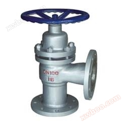
The flange angle plunger valve produced by Shanghai Guanhuan Valve Manufacturing Co., Ltd., U44SM flange angle plunger valve, has the same working principle as the straight through plunger valve, except that it is installed in a different position in the pipeline. Therefore, there are many corners and turns in long-distance pipelines such as petroleum, chemical, fertilizer, and pharmaceutical industries
Product Details
Produced by Shanghai Guanhuan Valve Manufacturing Co., LtdFlange angle plunger valve,The working principle of U44SM flange angle plunger valve is completely the same as that of straight through plunger valve, except that they are installed in different positions in pipelines. Therefore, there are many corners and turns in long-distance pipelines such as petroleum, chemical, fertilizer, and pharmaceutical industries. Champion quality, global world. And the angle type plunger valve is precisely installed at this location, which not only reduces the number of pipe bends, but also has the characteristics of easy installation, labor saving, and material saving.
Flange angle plunger valveWorking Principle:
The closing of U44SM flange angle plunger valve consists of a stainless steel plunger, two elastic sealing rings on top and bottom, and a metal partition frame. The sealing effect is achieved by the tight fit between the plunger and the sealing ring. The plunger is inserted into the two sealing rings, and the sealing area is much larger than that of a normal globe valve; When opening and closing the plunger valve, the plunger slowly moves in the sealing ring, and the contact surface is almost not worn. When closing, the plunger is inserted into the lower sealing ring, cutting off the flow channel; When opened, although the plunger is detached from the lower sealing ring, it is still hidden inside the upper sealing ring, maintaining isolation from the outside world and preventing leakage.
Flange angle plunger valveProduct Features:
1. Can be installed on horizontal or vertical pipelines.
2. The valve body material can be selected from high-temperature stainless steel or carbon steel.
3. The valve stem undergoes quenching and surface nitriding treatment, exhibiting excellent corrosion resistance and friction resistance; Good sealing results in more reliable performance.
4. The valve disc and valve stem are designed as an integrated structure to prevent the possibility of internal components rushing out of the valve body due to pressure fluctuations in the pipeline. The structure is compact and safe to use.
Flange angle plunger valveInstallation and maintenance:
1. This plunger valve can be installed at any position, and the direction of medium flow is indicated by the arrow on the valve body.
2. In pipelines with large temperature differences between hot and cold alternation in a short period of time, plunger valves cannot be used.
3. The plunger valves produced by our company are tested, accepted, and used according to ZBJ16006 before leaving the factory. Only the exterior and cavity need to be cleaned, and there is no need to disassemble, wash, or replace them.
4. After a period of use, if there is wear and leakage on the sealing ring, the valve must be closed first, and then the middle flange bolts should be slightly tightened evenly until there is no leakage. When replacing them at the same time, precautions should be taken to prevent cracks and damage to the plunger and the newly installed sealing ring.

Flange angle plunger valveMain appearance and connection dimensions
model |
Nominal diameter DN (mm) |
Main appearance and connection dimensions (mm) |
|||||||
L0 |
H |
W |
D |
D1 |
D2 |
b |
Z-Φ d |
||
|
U(J)44SM-16cP
|
15 |
65 |
190 |
100 |
95 |
65 |
45 |
12 |
4-14 |
20 |
75 |
210 |
100 |
105 |
75 |
55 |
12 |
4-14 |
|
25 |
80 |
220 |
120 |
115 |
85 |
65 |
12 |
4-14 |
|
32 |
90 |
250 |
140 |
135 |
100 |
78 |
13 |
4-18 |
|
40 |
100 |
280 |
160 |
145 |
110 |
85 |
13 |
4-18 |
|
50 |
115 |
300 |
180 |
160 |
125 |
100 |
13 |
4-18 |
|
65 |
145 |
320 |
200 |
180 |
145 |
120 |
15 |
4-18 |
|
80 |
155 |
340 |
240 |
195 |
160 |
135 |
17 |
8-18 |
|
100 |
175 |
420 |
280 |
215 |
180 |
155 |
17 |
8-18 |
|
125 |
200 |
440 |
320 |
240 |
210 |
185 |
19 |
8-18 |
|
150 |
240 |
530 |
350 |
280 |
240 |
210 |
21 |
8-23 |
|
200 |
300 |
610 |
400 |
335 |
295 |
265 |
23 |
12-23 |
|
250 |
325 |
730 |
520 |
405 |
355 |
295 |
27 |
12-25 |
|
300 |
375 |
850 |
640 |
460 |
410 |
385 |
28 |
12-25 |
|
350 |
394 |
970 |
460 |
520 |
470 |
435 |
30 |
16-25 |
|
400 |
457 |
1100 |
900 |
580 |
525 |
485 |
32 |
16-30 |
|
Flange angle plunger valveMain connection dimensions:
model |
Nominal diameter DN (mm) |
Main appearance and connection dimensions (mm) |
|||||||
L0 |
H |
W |
D |
D1 |
D2 |
B |
Z-Φ d |
||
|
U(J)44SM-25cP
|
15 |
65 |
190 |
100 |
95 |
65 |
45 |
14 |
4-14 |
20 |
75 |
210 |
100 |
105 |
75 |
55 |
14 |
4-14 |
|
25 |
80 |
230 |
110 |
115 |
85 |
65 |
14 |
4-14 |
|
32 |
90 |
260 |
140 |
135 |
100 |
78 |
15 |
4-18 |
|
40 |
100 |
260 |
160 |
145 |
110 |
85 |
15 |
4-18 |
|
50 |
115 |
290 |
180 |
160 |
125 |
100 |
17 |
4-18 |
|
65 |
145 |
320 |
200 |
180 |
145 |
120 |
19 |
8-18 |
|
80 |
155 |
370 |
240 |
195 |
160 |
135 |
19 |
8-18 |
|
100 |
175 |
420 |
280 |
230 |
190 |
160 |
21 |
8-23 |
|
125 |
200 |
460 |
320 |
270 |
220 |
188 |
25 |
8-25 |
|
150 |
240 |
530 |
350 |
300 |
250 |
218 |
27 |
8-25 |
|
200 |
300 |
610 |
400 |
360 |
310 |
282 |
31 |
12-25 |
|
250 |
325 |
730 |
520 |
425 |
370 |
345 |
33 |
12-30 |
|
300 |
375 |
850 |
640 |
485 |
430 |
408 |
36 |
16-30 |
|
350 |
394 |
970 |
760 |
550 |
490 |
465 |
40 |
16-34 |
|
400 |
457 |
1100 |
900 |
610 |
550 |
535 |
44 |
16-34 |
|