-
E-mail
oubeihaiyang.1688.com
-
Phone
13676799385
-
Address
No. 245 Linxia Road, Zhangbao Industrial Zone, Sanqiao Industrial Park, Wenzhou
Product Categories
Yongjia County Marine Water Pump Factory

H-150 slide valve vacuum pump
NegotiableUpdate on 03/18
- Model
- Nature of the Manufacturer
- Producers
- Product Category
- Place of Origin
Overview
H-150 slide valve vacuum pump is a slide valve mechanical vacuum pump, which is a vacuum pumping equipment for extracting general gases or gases containing a small amount of condensable steam (gas ballast device should be used).
Product Details
Model Meaning

Product Introduction
H-150 slide valve vacuum pump is a slide valve mechanical vacuum pump, which is a vacuum pumping equipment for extracting general gases or gases containing a small amount of condensable steam (gas ballast device should be used).
Performance specifications for H-150 slide valve vacuum pump: geometric pumping speed of 150L/S, ultimate pressure of 1Pa (8 × 10⁻³ Torr). Suitable for vacuum smelting, vacuum drying, vacuum coating, vacuum impregnation, and other vacuum operations. It can be used alone or as a pre pump for other vacuum pumps, but it is not suitable for pumping from one container to another as a transfer pump. When extracting gases with high oxygen content, explosiveness, corrosiveness to black metals, chemical reactions to vacuum oil, water, dust, etc., auxiliary devices should be added.
Structure and Principle
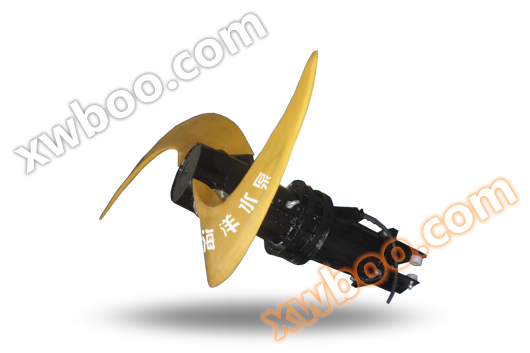
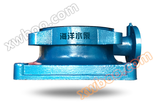
| The H-150 slide valve vacuum pump is mainly composed of a pump body, slide valve, eccentric wheel, etc. | |||||||||||||||
| Working principle diagram of H-150 slide valve vacuum pump | |||||||||||||||
|
|||||||||||||||
| Working principle of H-150 slide valve vacuum pump | |||||||||||||||
| A slide valve (4) is installed in the pump body (1), and an eccentric wheel (3) is installed inside the slide valve. The eccentric wheel is driven to rotate by a shaft (2) that leads to the outside of the pump cylinder, and the center of the shaft coincides with the center of the pump cylinder. The outer circle of the slide valve slides on the inner surface of the pump cylinder, and the upper part of the slide valve freely slides up and down and swings left and right in a semi-circular slide valve guide rail (5). Therefore, the pump cylinder is divided into two chambers, A and B, by the slide valve, as shown in the above figure. If the shaft rotates counterclockwise, chamber A gradually expands, chamber B gradually shrinks, and then chamber A becomes larger and chamber B becomes smaller. On the other hand, the upper part of the slide valve is hollow and has a rectangular hole on the A chamber side. During the expansion of the A chamber, gas flows into the pump chamber A through the hollow part of the slide valve and the rectangular hole. When the spool valve turns to the top dead center of the chamber, the original B chamber disappears and A chamber replaces B chamber, forming a new A chamber at the original A chamber position. At the final stage of compression in chamber B, the compressed gas is pushed open through the exhaust valve (6) and discharged out of the pump, and this cycle continues to form the operation of the pump. This type of pump is equipped with six sets of disc type exhaust valves (6) (see structural diagram). The exhaust valves are mainly composed of springs, valve plates and other parts. When the gas and oil in the pump chamber are discharged from the exhaust valve, they are separated by the oil blocking cap (3) in the oil tank (16), and the gas is discharged to the atmosphere. The oil is filtered by the oil filter (15) and then pumped into the small oil tank (15) by the oil pump (22) under strong pressure before being supplied to the bearings, slide valves, pump chamber and other movable parts. With the operation of the pump, the compressed gas and oil are discharged by the exhaust valve, so the lubrication of this type of pump is automatic. In addition to lubricating and sealing, pump oil also plays an important role, which is that when the amount of gas pumped is small, the exhaust valve can also work. The compressed small amount of gas and oil together push open the exhaust valve to achieve the purpose of exhaust. The pump body, pump covers A and B, eccentric wheel, slide valve, and slide valve guide rail are all made of high-strength cast iron. After rough machining, they undergo artificial aging treatment to eliminate internal stress, and then undergo precision machining to form the working chamber of the pump. The shaft is made of high-quality carbon steel and is equipped with an eccentric wheel in the middle; Fixed with a key, one end of the shaft is equipped with an oil pump impeller, and the other end is equipped with a pump V-belt pulley, which is connected to the motor through a V-belt. The joint surface between the rotating part and the intake part of the pump is sealed with rubber sealing rings, and the pump body and pump cover are sealed with paper pads and 107 resin or soft flat sealant. |

performance parameter
Geometric pumping speed |
L/S |
150 |
limiting pressure |
Pa |
1 |
Torr |
80×10-3
|
|
Pump shaft speed |
r/min |
450 |
Equipped with motor |
KW |
15 |
model |
Y180L-6 |
|
Steam productivity |
kg/h |
About 8.4 |
Long term operation pump inlet high pressure |
Pa |
1.3×10⁴
|
Cooling water consumption |
L/h |
700 |
lubricant |
brand |
1 # Vacuum mechanical pump oil |
Storage capacity kg |
30 |
|
caliber |
Inlet mm |
100 |
Exhaust mm |
80 |
|
volume |
Length×Width×Height |
1580×826×1285 |
weight |
kg |
680 |
| Note: The ultimate pressure of a pump refers to the maximum partial pressure of non condensable gases measured using a compression vacuum gauge. | ||
Structural diagram
 |
|||||
Serial Number |
name |
Serial Number |
name |
Serial Number |
name |
1 |
Exhaust port cover |
11 |
Long closed lid |
21 |
Outlet pipe |
2 |
Fuel plug |
12 |
axle |
22 |
Oil pump assembly |
3 |
Oil cap component |
13 |
Guide rail components |
23 |
Rolling bearing 42312 |
4 |
Exhaust hood |
14 |
Oil filter assembly |
24 |
Pump cover B |
5 |
Exhaust seat |
15 |
Oil circuit components |
25 |
1/2 "drain plug |
6 |
Exhaust valve component |
16 |
Fuel tank components |
26 |
balance wheel |
7 |
bottom cover |
17 |
Air intake cover |
27 |
Pump pulley |
8 |
pumping element |
18 |
Imported bent pipe |
28 |
Sealing components |
9 |
Spool valve |
19 |
water inlet |
29 |
A pump cover |
10 |
eccentric wheel |
20 |
Inlet and outlet water sealing cover |
||
Installment and use
1. The base of the pump should be installed on a concrete foundation, and there should be a groove of 5 to 10 centimeters around the foundation to prevent contamination of the workshop during oil or water discharge.
2. When installing the H-150 slide valve vacuum pump, it is necessary to first calibrate the level, and then tighten the foot screws.
3. Before use, all dust and dirt on the pump must be removed, and the pump room must be kept clean regularly. The ambient temperature should be within the range of 5-40 ℃.
4. The suction port of the pump should be equipped with dust-proof devices according to the usage situation to prevent the suction of hard substances such as glass fragments, sand, metal sheets, or oxides. When assembling the vacuum system, attention should also be paid to these impurities. Due to the small gap between the slide valve and the inner wall of the pump chamber, impurities are not allowed to enter. Once impurities enter, serious accidents may occur, so measures must be taken in advance. For example, setting up dust prevention devices.
5. When the pump is operating under a coarse vacuum (when the inlet pressure exceeds 133 Pa (torr)), the exhaust hole should discharge oil mist in the same shape as smoke. The causes of oil mist are as follows: when the pump is operating under a coarse vacuum, the pressure of the compression chamber increases significantly, and the discharged gas is violently flushed out from the small exhaust 13. The oil near the orifice and exhaust valve is atomized according to the same principle as the spray, and is discharged out of the pump together with the gas. Regardless of the size of the phenomenon, this oil mist is basically present. In addition, the generation of this oil mist does not have any adverse effects on the pump. However, this oil mist spreads into the indoor air, not only polluting the air, but also damaging the indoor floor and appliances. To prevent this kind of pollution, the exhaust pipe needs to be connected to the outside during installation. The outlet of the outdoor exhaust pipe should face downwards to avoid rainwater dripping in.
6. The intake duct should be very tight, even a small leak can affect the vacuum level.
In principle, the intake pipeline should be as short as possible, with fewer joints and elbows. The pipeline connected to the pump should not be smaller than the diameter of the pump.
7. Valves should be installed on the inlet pipeline of the cooling water, which can be adjusted slightly. The temperature of the cooling water in the pump water jacket should be controlled between 20-40 ℃ during operation, and attention should be paid to the water temperature not exceeding 40 ℃ to avoid the formation of scale inside the water jacket.
8. If the extracted gas is above 40 ℃, the gas should be cooled to room temperature.
9. When the pump is working, the temperature should not exceed 85 ℃.
10. When the pump is operating under normal conditions, the oil level should be within about half of the range indicated on the oil tank gauge. If it is insufficient, it should be refilled with oil.
11. When changing the oil in the pump, about 1kg of oil should be added to the pump inlet, and the remaining oil should be added through the refueling hole on the oil tank.
12. Apply a clearance height of 300mm above the pump, that is, connect a 300mm high pipe at the pump exhaust port first. Connect the exhaust passage again. In this way, when disassembling the pump, only the pipes need to be removed without moving the exhaust passage, and the fuel tank can be disassembled.
Start and Stop
1、 Preparation before startup
(1) Check the tightness of the belt. Loosen it before starting. After starting, adjust the adjusting bolt on the base and slowly tighten it to reduce the starting torque.
(2) Check for any looseness in each part and whether the motor direction meets the requirements of the pump.
(3) Check if the oil level in the fuel tank is about half of the oil gauge on the tank.
(4) For pumps that have not been working for a long time, the method of intermittent starting the motor should be used before starting to check whether the rotation is flexible.
(5) Open the cooling water valve.
(6) In winter, if the room temperature is too low, the pump should be warmed up before starting. Due to the high viscosity of the oil at low temperatures, sudden starting can overload the motor and damage the pump components.
(7) If there is a significant difference between the oil level on the oil mirror on the fuel tank and the oil level when parking, the pump pulley must be rotated to allow the stored oil in the pump chamber to be discharged into the fuel tank before starting. When there is a large amount of oil stored in the pump chamber under vacuum, the pump is not allowed to start.
2、 Start up
(1) Close the power switch and start the motor.
(2) Check if the cooling water and lubricating oil are normal.
(3) After running for about five minutes and everything is normal, slowly open the intake valve to avoid a sharp increase in pump load.
3、 Parking
The parking of the pump is particularly important, otherwise it will be difficult to start next time. The principle of parking should be carried out according to the following procedures:
(1) Close the intake valve on the intake pipeline.
(2) Open the inflation valve to break the vacuum inside the pump.
(3) Wait for about half a minute and cut off the power.
The above procedures cannot be taken lightly, otherwise when the pump is stopped, due to the vacuum in the pump chamber, the oil in the oil tank will continuously flow into the pump chamber, filling the pump chamber with oil. From the perspective of parking, this is not a big danger, but when starting again, there is a problem. That is, when driving with the pump cylinder filled with oil, almost all the oil in the rotor needs to be flushed out from the exhaust port when it rotates the first circle. On the other hand, because the oil can hardly be compressed and has a high viscosity, it will be squeezed out of the small exhaust port of the pump at once, and the resistance is very large. Therefore, the electric motor requires a very large starting torque, and in an instant, it increases the huge impact force on the shaft and eccentric wheel, which is very important for the pump and motor. Dangerous, especially when the ambient temperature is low. If operated according to the above procedure, the above dangers can be avoided.
precautions
1、 Maintenance
(1) Regular attention should be paid to the oil level and oil cleanliness. The new pump should be changed after 150 hours of operation, and then every 2-3 months thereafter. If the usage conditions are poor and the vacuum degree decreases, the oil change time can be shortened.
(2) Pumps and pump rooms should be kept dry and clean regularly.
(3) Regularly pay attention to the temperature of the pump, as well as the temperature of the cooling water and oil.
2、 Precautions
(1) In cold regions, all water in the cooling water jacket must be drained after parking, otherwise it will freeze the water in the jacket and damage the pump casing.
(2) Lubricating oil should be used as mechanical vacuum pump oil (i.e. SY1634-76,1 vacuum pump oil specified by the Ministry of Petroleum, code KK-1), otherwise the required vacuum degree cannot be achieved.
(3) Pay attention to the cleanliness of the oil and regularly clean the copper wire mesh in the oil filter.
(4) If not in use for a long time, turn on the pump every 7-10 days for about an hour to prevent rusting inside the pump.
Disassembly and assembly
Disassembly procedure: (Water and oil should be drained first)
(1) Protective cover.
(2) Pump V-belt pulley, balance wheel
(3) Oil pipes and oil pumps.
(4) Bearing cover and sealing device
(5) Pump covers A and B (remove the bearings together).
(6) Slide valve and slide valve guide assembly.
(7) Eccentric wheel, flat key, and shaft.
Exhaust valve disassembly procedure:
(1) Bolt
(2) Valve cover
(3) Valve body
(4) The remaining parts will separate on their own. When assembling, the order is reversed.
Attention should be paid to disassembly and assembly:
(1) Do not directly use a hammer to strike the machined surface.
(2) Prevent bumping and knocking.
(3) When installing, carefully clean the parts until there are no stains on them when wiped with a white cloth.
(4) Be careful not to leak or leak oil on the sealing surface.
Fault symptoms and troubleshooting methods
Fault phenomenon |
cause |
Troubleshooting |
1. Low vacuum degree |
(1) Oil is contaminated (2) Leakage of sealing device (3) Oil pipe joint leakage (4) The exhaust valve plate is damaged (5) The exhaust valve spring is broken (6) Each sealing surface leaks air (7) There is impact, clamping, and abnormal noise inside the pump (8) Oil circuit blockage (9) Inhalation gas temperature is too high (10) Insufficient pump oil volume |
(1) Open the gas damper and run for 1-2 hours to restore the maximum pressure of the pump or replace all the new oil (2) Repair or replace the sealing device (3) Tighten the nut (4) Replace the valve plate with a new one (5) Replace the spring with a new one (6) Tighten the screws (7) Repair the slide valve guide rail and clean all parts (8) Clean the oil filter screen and oil circuit (9) Cool to room temperature (10) Keep going |
2. Rotation malfunction |
(1) Excessive motor load or blown fuse (2) Lack of lubricating oil (3) External object clamping (4) Great vibration |
(1) Find out the cause of overload and burnout, replace the fuse (2) Smooth the oil circuit and disassemble and clean the parts inside the pump. Add vacuum oil (3) Remove external debris (4) Strengthen the foundation base and check the fastening bolts |
3. Operational accidents |
(1) Bearing overheating (2) The exhaust valve and oil pipe are heating up |
(1) Loosen the belt slightly or check if the oil circuit is blocked and if the cooling water is sufficient (2) Open the cooling water valve |
4. Abnormal noise during pump operation |
(1) Foreign objects fall into the pump (2) Loose or damaged pump components |
(1) Disassemble, inspect and remove (2) Check, adjust or replace parts |
Similar Product Recommend