-
E-mail
1769283299@qq.com
-
Phone
15666889252
-
Address
Room 207, Building 1, Weifang High tech Zone Optoelectronic Industry Accelerator (Phase I), No. 155 Optical Circuit, Weifang High tech Zone, Shandong Province
Product Categories
Shandong Jingdao Optoelectronics Technology Co., Ltd


Lightning Monitoring and Warning System
NegotiableUpdate on 02/22
- Model
- Nature of the Manufacturer
- Producers
- Product Category
- Place of Origin
Overview
The core indicators monitored by the lightning monitoring and early warning system include the number of cloud to ground lightning strikes, peak lightning current (in kiloamperes, kA), lightning positioning accuracy (usually up to 1-5 kilometers), and warning time (usually 15-30 minutes, which can be extended to 1 hour in some cases). These data together form a "dynamic portrait" of lightning activity, laying the foundation for accurate warning.
Product Details
Lightning Monitoring and Warning SystemThe core indicators of its monitoring include the number of cloud to ground lightning strikes, peak lightning current (unit: kiloampere, kA), lightning positioning accuracy (usually up to 1-5 kilometers), and warning time (usually 15-30 minutes, which can be extended to 1 hour in some cases). These data together form a "dynamic portrait" of lightning activity, laying the foundation for accurate warning.
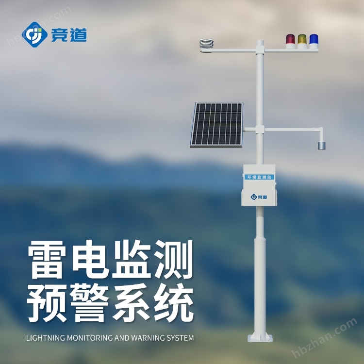
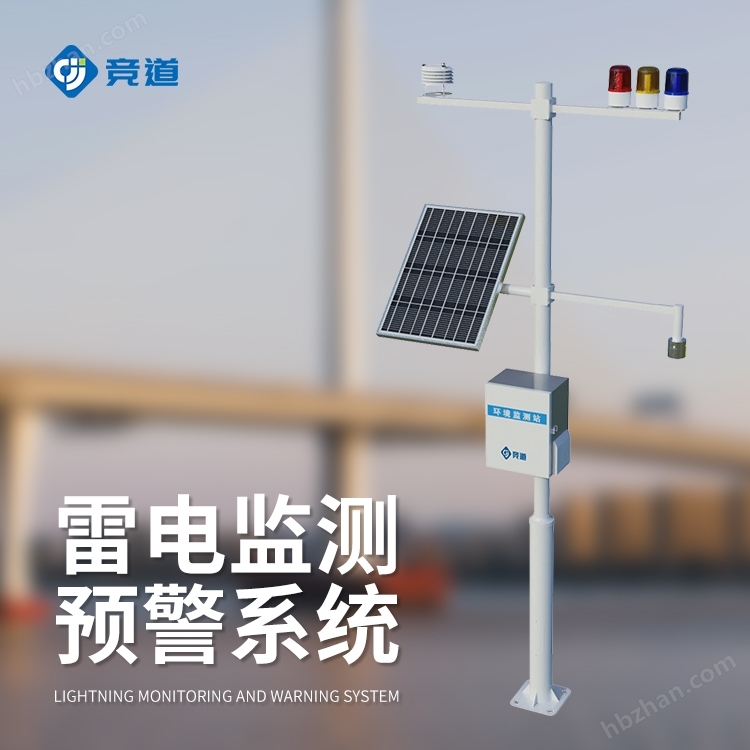
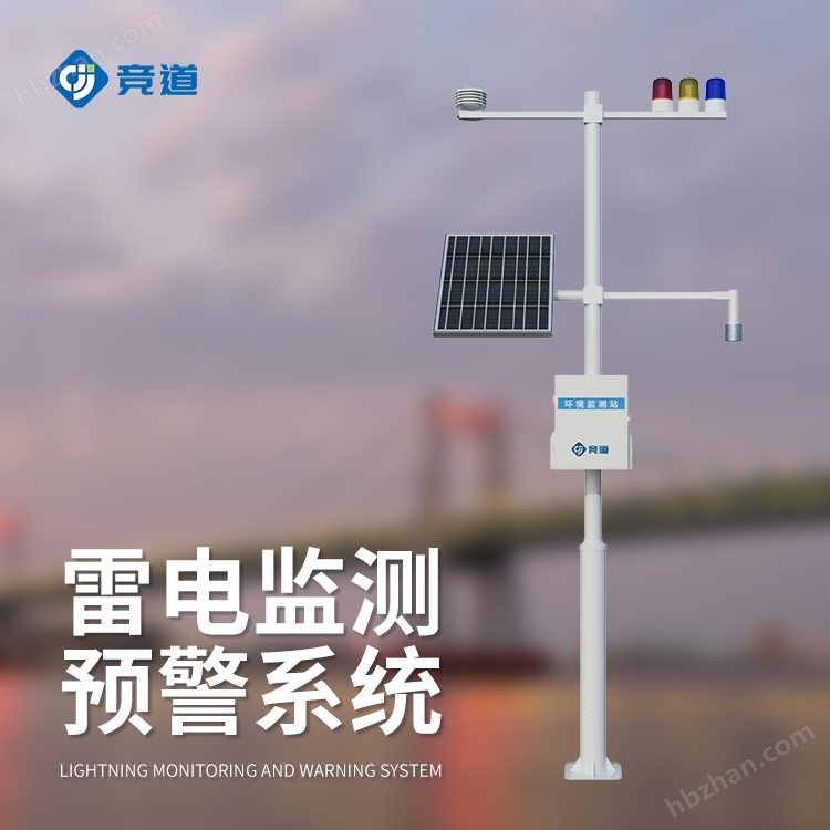
1、 Product Introduction
Lightning Monitoring and Warning SystemIt is a fully digital electric field detection and lightning warning platform. Its core electric field detection structure is based on the principle of charge induction and developed using MEMS (Micro Electro Mechanical Systems) technology. It has no easily worn and movable mechanical components such as motors, and has outstanding advantages such as small size, low power consumption, high reliability, and easy integration. The system adopts electric field differentiation combined with threshold threshold optimization for lightning warning algorithm. Compared with the conventional threshold method, it is more likely to avoid false alarms caused by human interference (rainy/windy/snowy/dusty), further improving the accuracy of warning. The lightning warning monitoring system provides accurate warning, is easy to network, and is easy to install. It is mainly aimed at the application needs of atmospheric electric field detection and lightning local short-term warning in fields such as aerospace defense, meteorology, petroleum and petrochemical, power grid, scenic spots, mines, oil depots, and military.

2、 Product composition
1. Lightning warning probe
2. Data processing host
3. Solar power supply system
4. Surge system
5. Grounding system
6. Air temperature, humidity, and atmospheric pressure sensors
7. Sound and light alarm level 3
8. Cloud data query and real-time display
3、 Product Features
1. Users can connect the lightning warning monitoring system probe to the cloud server to achieve remote monitoring
2. By analyzing the data, make more accurate judgments on the strength and polarity changes of the thunderstorm electrostatic field
3. This system can be connected to the sound and light alarm system
4. The system software has complete network transmission functions; The transmission of data follows network protocols
4、 Technical parameters
| device name | Lightning warning and monitoring system |
| Electric field measurement range | -100kV/m~100kV/m |
| resolution | 0.1V/m |
| accuracy | ±0.001%F.S |
| Detection distance (radius) | 15KM |
| Total weight | 36KG |
| sensor weight | 710g |
| input voltage | DC12V |
| power consumption | 12VDC( 2W@12V )(System) |
| size | 105 * 78mm (sensor); 3m (pole support) |
| Operating Temperature | -10 ℃~60 ℃ (sensor); -40 ℃~80 ℃ (controller) |
| Deployment location (indoor/outdoor) | outdoors |
| Shelf height | 2m (bracket) (sensor installation height 1.8m) |
| Management interface type | RS485 Modbus RTU (sensor); RS485 json/RS485 Modbus RTU (controller) |
| Alarm linkage (control) function | Level 3 warning |
| Number and types of data interfaces | 3 aviation sockets, 1. power supply, 2. RS485 json, 3. RS485 Modbus RTU |
| GPRS data traffic demand | 100M/month |
| External data frequency | 60s |
| Outbound Data Communication Protocol (Broadcast) | json |
5、 Installation precautions
1. Lightning warning probes should be installed on sunny days
2. Lightning warning probes should be installed outdoors without obstruction or surrounding obstructions
3. It shall not be installed at the exhaust outlet of the generator, next to the power pole, or under the high-voltage line
4. Under abnormal circumstances, when protruding from the ground, close to antenna poles or other equipment, the field strength and its test data may be interfered with
5. In wired mode, the wiring distance from the outdoor electric field meter probe to the indoor host is not recommended to exceed 100 meters
6. The equipment should have good grounding during use
7. More about our company
8. If there are any parameter updates, no further notice will be given, and the technical interpretation rights belong to our company
6、 Installation steps
1. Take out the complete set of lightning warning and monitoring system from the box
2. Fix the bracket to the designated installation position and secure it with bolts
3. Connect the lightning rod (optional) top grounding point to the grounding wire, and the other end of the grounding wire is introduced from the inside of the bracket and led out from the bottom hole of the bracket. After installing the grounding electrode and other grounding devices, connect the lightning rod grounding wire
4. Introduce the wires of the atmospheric electric field meter probe and the temperature, humidity, and pressure sensor from the inside of the bracket, lead them out through the hole in the middle of the bracket, and connect them to the main control box. There is an expansion box inserted into the main control box,
5. Fix the solar panel onto the bracket and connect the solar wires to the photovoltaic controller according to their colors
7. Connect the battery to the photovoltaic controller
8. Connect the control wires of the three color sound and light alarm lights to the alarm control module according to their respective colors
9. Contact after-sales service through the device number on the equipment box to obtain a login account
10. Open the computer and log in to the cloud platform through a browser (Google or Huawei Browser) to view data