-
E-mail
479333214@qq.com
-
Phone
15857728857
-
Address
Jiaoxia Industrial Zone, Oubei Town, Wenzhou City, Zhejiang Province
Product Categories
Zhanye Valve Co., Ltd


Pneumatic penetrating knife gate valve
NegotiableUpdate on 03/09
- Model
- Nature of the Manufacturer
- Producers
- Product Category
- Place of Origin
Overview
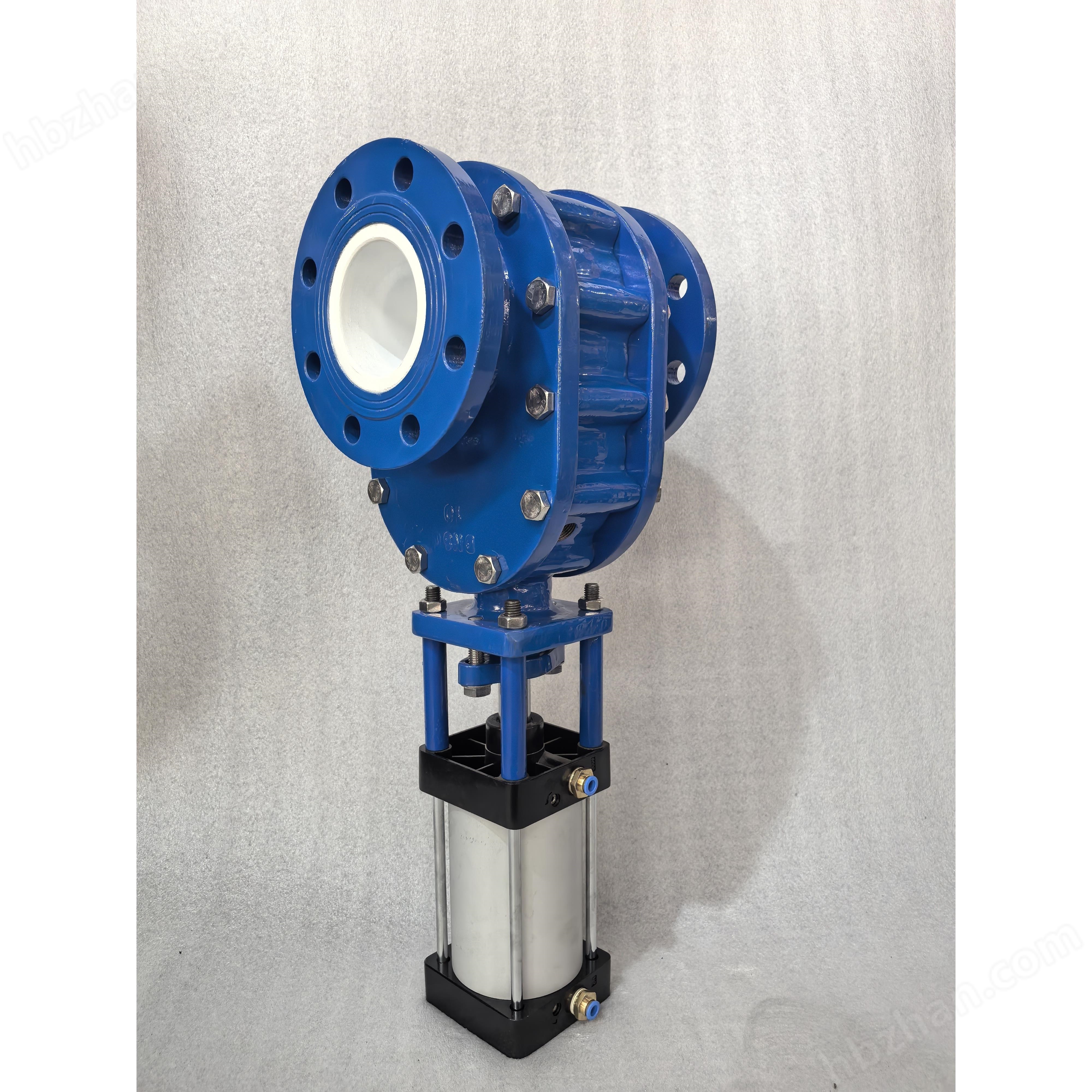
Pneumatic penetrating knife gate valve is suitable for nominal pressures ranging from 0.6MPa to 1.6MPa and temperatures ranging from -40 ℃ to 1000 ℃. It has two types of structural forms: hard seal and soft seal, with good sealing performance. The valve body is made of carbon steel or stainless steel material, with high pressure resistance and good wear resistance of the sealing surface. It is easy to install, has less jamming and ash deposition, and has a long service life.
Product Details
Pneumatic penetrating knife gate valveSuitable for use in power plants, mines, papermaking, metallurgy, chemical engineering, sewage treatment, and other industries for opening, closing, or regulating flow in pipelines containing abrasive and corrosive slurries and particles. Suitable for nominal pressures ranging from 0.6MPa to 1.6MPa and temperatures ranging from -40 ℃ to 1000 ℃, the structure is divided into two types: hard seal and soft seal, with good sealing performance. The valve body is made of carbon steel or stainless steel material, with high pressure resistance and good wear resistance of the sealing surface. It is easy to install, with few instances of sticking or scaling, and has a long service life.
Explanation of Valve Model Compilation Method
Pneumatic penetrating plug valve SCZ673H (Y/X/F) -10 (16) C (P/R/RL/NR)
Valve type code: "SCZ" represents a through type gate valve;
Transmission form code: "6" represents pneumatic;
Connection form code: "7" indicates clamp type connection (our factory also has flanges for clamp type valves, just like flange type connections)
Structural form code: "3" represents a parallel single gate with a visible rod;
Material code for sealing surface: "H" represents alloy seal, "Y" represents hard alloy seal, "X" represents rubber seal, and "F" represents PTFE seal;
Valve nominal pressure: Its value is 10 or 16 times the nominal pressure value in MPa;
Valve body material code: "C" represents carbon steel, "P" represents 304 stainless steel, "R" represents 316 stainless steel, "RL" represents 316L stainless steel, and "NR" represents 2520 stainless steel;
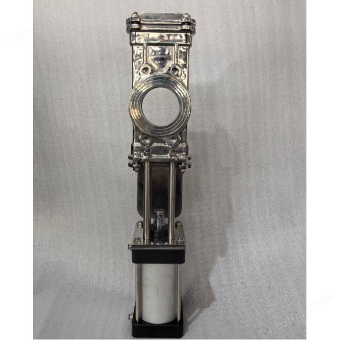
Pneumatic penetrating knife gate valveworking principle
When the air source is introduced from the upper intake port, the valve stem drives the valve plate to move downward and the valve closes. When the gas source is introduced from the lower air inlet, the valve stem drives the valve plate to move upward, and the valve opens.
Product Features
The fully circular DC channel design has no slag or blockage. The valve plate can achieve the best sealing effect through precision grinding and polishing treatment. Compact design, small space occupation, light weight, affordable price, easy installation, complete wear-resistant and anti blocking measures, easy maintenance, convenient use and long service life, and can freely choose other driving devices.
The valve body and packing culvert are both precision cast, with the valve body being cast as a whole and materials such as WCB, 304, 316, 316L, 2520 can be selected according to user needs. The packing is made of graphite packing and PTFE polytetrafluoroethylene material, which is corrosion-resistant, wear-resistant, and slag free.
Scope of application:
Mining, coal washing, steel industry - used for washing coal pipelines, filter slurry pipelines, and ash discharge pipelines;
Purification device - used for rainwater, wastewater, mud, dirt, and clarified water with suspended solids;
Paper industry - used for any concentration of pulp, feed water mixture;
Power plant ash removal - used for ash slurry.
Technical Specifications:
L nominal diameter: DN100-DN600 (can also be customized according to customer needs);
L nominal pressure 0.6-1.6MPa;
Applicable temperature: Soft seal: -20 ℃~200 ℃, carbon steel: -29 ℃~425 ℃, stainless steel: -40 ℃~500 ℃, heat-resistant stainless steel: ≤ 1000 ℃;
Applicable media: fly ash, gold ore powder, tailings, pulp, wood pulp, fiber, dust, rainwater, chemical treatment wastewater, sedimentation tank, mineral sand, slag, coal slurry, asphalt, silo outlet, fruits, grains, cement slurry, slaughterhouse wastewater, etc.
Execution standards:
Design according to JB/T869l
Flanges according to JB/T79
The structural length shall be in accordance with GB/T12221
Testing and acceptance shall be conducted in accordance with GB/T13927
Main component names and materials
serial number |
Part Name |
Material Description |
|
name |
material |
||
1 |
valve stem |
Carbon steel, stainless steel |
45 #, 304, 316, etc |
2 |
support |
Carbon steel, stainless steel |
WCB, CF8, etc |
3 |
ram |
stainless steel |
201、304、316、316L、 2520, etc |
4 |
gland |
Carbon steel, stainless steel |
WCB, CF8, CF8M, CF3M, 310S, etc |
5 |
filler |
Flexible graphite packing, PTFE packing |
|
6 |
sealing seat |
— |
Rubber or overlay alloy, stainless steel |
7 |
valve body |
Carbon steel, stainless steel |
WCB、CF8(304)、CF8M(316)、CF3M(316L)、310S(2520)等 |
Precautions for installation, use, and maintenance
Please place it in a dry and clean room. After long-term storage, it should be cleaned before installation, and all bolts should be checked for looseness.
Before installation, carefully read this instruction manual and verify the valve model, diameter, and technical parameters.
It is strictly prohibited to weld flanges after installing the valve to avoid damaging the valve sealing ring. The installation distance of valves reserved between pipelines should be appropriate, and gaskets should be added on both sides of the flange. The installation should ensure that the valve is easy to operate, maintain, and replace.
The centers of the two pipelines and the diameter center of the valve should be kept coaxial, and the flange surface should be flat without significant deviation to ensure the clamping and normal operation of the valve. Tighten the bolts evenly and symmetrically.
During the loading and unloading process, slings are not allowed to be used on handwheels, cylinders, and valve stems.
Possible faults and solutions
Fault phenomenon |
root cause |
Prevention and solutions |
The valve does not operate or the switch is not in place |
1. The packing is pressed too tightly and skewed |
Adjust the tightness of the nut on the packing cover |
2. There is dirt and dust stuck between the valve body and the valve plate (inside the valve chamber) |
Cleaning and repairing to remove dirt, extending the air delivery time |
|
3. Wear of valve stem, valve stem nut or bending deformation of valve stem |
Replace the valve stem and valve stem nut |
|
4. Insufficient gas source pressure (pneumatic) |
Increase the pressure of the gas source |
|
5. Is the cylinder barrel damaged (pneumatic) |
Check if the cylinder barrel is out of roundness, and replace it if it is damaged |
|
6. Electromagnetic valve or travel switch signal malfunction (pneumatic) |
Check or replace solenoid valves and travel switches |
|
7. Electric actuator limit fault or failure to operate (electric) |
Check or replace the electric actuator |
|
Leakage at the filling point |
1. The packing is not tightly compressed |
Tighten the nut on the packing gland |
2. Filler failure |
Replace the packing material |
|
Sealing surface leakage |
1. The handwheel has not reached the bottom |
Tighten the handwheel |
2. The sealing surface is worn or contaminated |
Disassemble, repair, grind the sealing surface or remove dirt |
Ordering Instructions
1. If the model has not been selected before ordering, please provide the corresponding technical parameters, such as pipeline diameter, medium type, medium temperature, working pressure, connection method, installation method, ambient temperature, and other special functional requirements. We will communicate with you in a timely manner to confirm the corresponding model.
2. If our company's products are selected by the design institute or unit department, they shall be ordered from our company according to the specified model, and corresponding technical parameters shall also be provided.
3. When the operating conditions are very important or the pipeline system is complex, please provide a pipeline installation diagram and detailed parameters for joint communication and review by both parties.