-
E-mail
1906680014@qq.com
-
Phone
13952500168
-
Address
Xingyuan 1st Road, Chengnan Industrial Park
Product Categories
Baofei Vibration Instrument Factory in Baoying County


Vibration controller
NegotiableUpdate on 02/10
- Model
- Nature of the Manufacturer
- Producers
- Product Category
- Place of Origin
Overview
Vibration controller panel description: The front panel of $r $n includes a touch screen and an Input input interface. The touch screen allows users to input vibration frequency, displacement setting value (Sv) (other parameters can also be modified), and set standard sensor sensitivity. The Input interface provides users with access to standard sensors.
Product Details
Vibration controllerPanel Description
The front panel includes a touch screen and an Input input interface. The touch screen allows users to input vibration frequency, displacement setting value (Sv) (other parameters can also be modified), and set standard sensor sensitivity. The Input interface provides users with access to standard sensors.
The rear panel includes an exciterOutputinterface220VPower supply and power switchRS485Interface.
Setting up, wiring, and usage
1. Set standard sensor sensitivity
After connecting the power, press the power button. The screen lights up. Click on the screenSettingButton, appearingPASSWORDInterface, click on the number00000The number input interface appears, enter13145Click OK in sequence to enter the sensitivity setting andPID_kpInterface. Below the interfacePID_kpIt has been set up and generally does not need to be modified. Above the interfaceSensorCan input standard sensor sensitivity, factory set to3.5PC/(m/s^2)According to the actual sensitivity value of the standard sensor, after modifying the value, be sure to clickOK.
1. Set vibration frequency and displacement settingsSv
clickFrequencyThe red number next to it sets the frequency. clickDisplacement SvNext to the red number, set the displacementSvValue. The limit values for displacement settings at each frequency are shown in the table below
Max Displacement(um) |
|
20Hz |
3700 |
30Hz |
4200 |
40Hz |
3500 |
50Hz |
3300 |
60Hz |
2600 |
70Hz |
2500 |
80Hz |
2200 |
90Hz |
1500 |
100Hz |
1100 |
As the displacement increases, the service life of the spring will be reduced.
2. wiring
Use cables to connect the back panel of the controllerOutputConnected to the exciter.
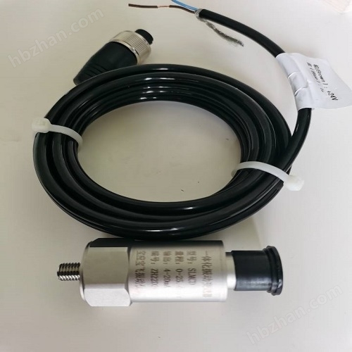
Install the standard sensor at the bottom of the exciter. with double headsL5The cable connects the standard sensor and controller front panelInputEnd.
1. Controller output signal
After connecting the exciter and standard sensor with cables and setting the parameters on the touch screen, you can click on the button on the touch screenStartOutput signal.
Displacement PvThe displayed next to it is the actual vibration displacement value of the exciter.
ZDK-20 Vibration Controller


MODBUSView displacementPvvalue
1. 485connect the dots
According to the rear panel of the controllerA(+)andB(-)Identification, Connection485Communication cables.
2. Displacement display
According to the table belowMODBUSCommunication parameters and address allocation table, view the actual displacement value of the exciter.
Communication |
MODBUS RTU |
slave ID |
1 |
baudrate |
9600 |
data |
8 |
parity |
N |
stop |
A(1) |
Input Registers |
|||
address |
name |
data type |
unit |
30000 |
displacement |
U16 |
um |