-
E-mail
services@kmsbc.cn
-
Phone
13908719531
-
Address
494 Bailong Road, Kunming City, Yunnan Province
Product Categories
Kunming Pump Factory

KBS single-stage double suction open pump
NegotiableUpdate on 03/24
- Model
- Nature of the Manufacturer
- Producers
- Product Category
- Place of Origin
Overview
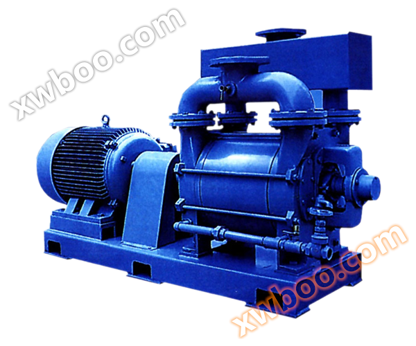
1、 Overview: KBS pump is a new generation of high-performance single-stage double suction open centrifugal pump. The pump uses an excellent hydraulic model, which increases the efficiency of the pump by 2-3% compared to similar pumps, greatly reducing the operating cost of the pump. The vacuum height is increased by 1-3 meters, thereby reducing civil engineering investment and extending the service life
Product Details
1、 Overview
The KBS pump is a new generation of high-performance single-stage double suction open type centrifugal pump. The pump uses an excellent hydraulic model, which increases the efficiency of the pump by 2-3% compared to similar pumps, greatly reducing the operating cost of the pump. The vacuum height is increased by 1-3 meters, thereby reducing civil engineering investment and extending the service life. The inlet and outlet are on the same straight line, and the same rotor can run in reverse. The support spacing between the two ends of the water pump is short, the pump runs stably, has low vibration and noise, and can be operated at an appropriate speed, making the water pump more adaptable to a wider range. The pump body can be installed vertically or horizontally according to the changes in use, mainly used in water plants, air conditioning circulating water, heating pipe network systems, building water supply, irrigation, drainage pump stations, power plants, industrial water supply systems, fire protection systems, shipbuilding industry, mining water supply and drainage, etc. It is a comprehensive replacement product of SH, S, SA, SLA, SAP type split double suction pumps.
2、 Model meaning
KBS 250-480 A-L - R (M, F) - J
| KBS | — | Kun Pump's new single-stage double suction open pump |
| 250 | — | Pump outlet diameter |
| 480 | — | impeller diameter |
| A | — | impeller has been cutted first |
| L | — | Vertical installation |
| R | — | Hot water type |
| M | — | Wear-resistant type |
| F | — | Corrosion resistant type |
| J | — | The shaft seal is a mechanical seal |
3、 Main technical parameters
Pump outlet diameter: DN=80~800mm
● Flow rate: Q=22~11660m3/h
Head: H=7~200m
● Working temperature: T=-20 ℃~105 ℃ (KBS type)=-60 ℃~200 ℃ (KBS-R type)
Solid particles: ≤ 80mg/l
● Allowable working pressure: ≤ 2.5Mpa (KBS type) ≤ 4Mpa (KBS-R type)
4、 Structural description
1. Structure
The inlet and outlet are on the same straight line, and the same rotor can run in reverse. The support spacing between the two ends of the water pump is short, and the pump runs stably with low vibration and noise. It can also run at an appropriate speed, making the water pump more adaptable to a wider range. The water pump can be equipped with an intermediate bracket, thickened pump body, sealed cooling, and bearing lubrication, making it suitable for operating at temperatures up to 200 ℃, especially for the requirements of heating pipe networks. The pump body can be installed vertically or horizontally according to changes in usage conditions, and mechanical seals or packing seals can be used for sealing.
2. Technical advantages
The support spacing between the two ends of the water pump is short, the pump runs stably, has low vibration and noise, and can be operated at an appropriate speed, making the water pump more adaptable to a wider range.
The inlet and outlet are on the same straight line, making the pipeline layout simple, convenient, and beautiful.
The same rotor can run in reverse, reducing the risk of water hammer causing damage to the water pump.
The unique high-temperature design of the water pump includes an intermediate support, thickened pump body, sealed cooling, and bearings lubricated with thin oil, making it suitable for operating at temperatures up to 200 ℃ and particularly suitable for use in heating pipelines.
The pump body can be installed vertically or horizontally depending on the usage, and mechanical seals or packing seals can be used for sealing.
The appearance of the water pump is designed with industrialization, with clear lines that conform to modern aesthetic standards.
3. Cost advantage:
By selecting an excellent hydraulic model, the efficiency of the pump is 2-3% higher than that of similar pumps, greatly reducing the operating cost of the pump.
The vacuum height is increased by 1-3 meters, thereby reducing civil engineering investment and extending the service life.
Imported bearings are selected, and parts materials can be chosen according to user requirements, enabling the pump to adapt to various on-site operating conditions and greatly reducing maintenance costs.
4. Maintenance advantages:
Containerized mechanical seals make replacing mechanical seals an easy and simple task.
The application of elastic prestressing assembly makes the assembly and disassembly of rotor components simple and quick.
No need to adjust various clearances during assembly.
5、 Pump structure diagram
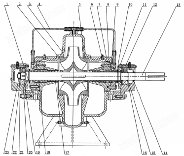
1. Pump body 2, impeller 3, pump cover 4, water flushing pipe component 5, sealing ring
6. Pipe plug 7, O-ring seal 8, sealing body 9, sealing gland or packing gland 10, water blocking ring
11. Bearing gland 12, bearing body 13, shaft 14, skeleton oil seal 15, elastic retaining ring
16. Bearing retaining ring 17, shaft sleeve 18, mechanical seal or packing seal 19, bearing sleeve 20, bearing
21. Bearing washer 22. Butterfly spring 23. Lock nut
6、 Material List of Main Components
| Part name | Material name | code |
| case of pump | Grey cast iron | HT250 |
| nodular cast iron | QT400-18 | |
| cast steel | ZG230-450 | |
| impeller | bronze | ZCuSn10Pb1 |
| Grey cast iron | HT250 | |
| silicon brass | ZCuZn16Si4 | |
| stainless steel | ZC0Cr18Ni12Mo2Ti | |
| axle | stainless steel | 2Cr13 |
| carbon steel | 45 | |
| Pump body sealing ring | bronze | ZCuSn5Pb5Zn5 |
| Grey cast iron | HT250 | |
| silicon brass | ZCuZn16Si4 | |
| stainless steel | ZC0Cr18Ni9Ti |
7、 Performance parameter table
| Model number | internet traffic | lift | rotational speed | efficiency | Motor Power | Necessary gas | quality | |
| Q | H | n | η | Corrosion allowance | m | |||
| m3/h | m | r/min | % | kW | m | kg | ||
| 80-210 | 50.1 | 16 | 1450 | 75 | 5.5 | 1.6 | 278 | |
| 83.5 | 13.8 | 82 | ||||||
| 100.2 | 12.4 | 80 | ||||||
| A | 46.3 | 13.8 | 74 | 4 | ||||
| 77.2 | 11.8 | 81 | ||||||
| 92.6 | 10.5 | 80 | ||||||
| B | 42 | 11.8 | 72 | 3 | ||||
| 70.4 | 9.8 | 80.5 | ||||||
| 84 | 9 | 78 | ||||||
| C | 38.6 | 10 | 72 | 3 | ||||
| 64.4 | 8.2 | 78 | ||||||
| 77.3 | 7 | 76 | ||||||
| 98.7 | 64.8 | 2900 | 75 | 37 | 4.5 | 278 | ||
| 164.5 | 55 | 82 | ||||||
| 197.4 | 49 | 80.5 | ||||||
| A | 97.7 | 56 | 74 | 30 | ||||
| 152.9 | 47.5 | 81 | ||||||
| 183.5 | 42 | 80 | ||||||
| B | 83 | 47.5 | 73 | 30 | ||||
| 138.5 | 39 | 80.5 | ||||||
| 166.2 | 36 | 79 | ||||||
| 80-210 | C | 77.4 | 41 | 2900 | 72 | 22 | 4.5 | 278 |
| 128.4 | 33.5 | 77.8 | ||||||
| 154 | 30 | 76 | ||||||
| 80-270 | 60.5 | 25.8 | 1450 | 73 | 11 | 2.3 | 293 | |
| 100.8 | 22.8 | 78.5 | ||||||
| 121 | 20.5 | 76 | ||||||
| A | 57.6 | 22.4 | 72 | 11 | ||||
| 96 | 19.3 | 77 | ||||||
| 115.2 | 17.4 | 74 | ||||||
| B | 52.9 | 18.8 | 70 | 7.5 | ||||
| 88.1 | 16 | 76 | ||||||
| 105.7 | 14.3 | 74 | ||||||
| C | 47.6 | 15.7 | 68 | 5.5 | ||||
| 79.4 | 13 | 75 | ||||||
| 95.3 | 11.6 | 73 | ||||||
| 124.8 | 102.5 | 2900 | 73 | 75 | 6.3 | 293 | ||
| 208 | 90 | 78.5 | ||||||
| 249.6 | 79 | 75.5 | ||||||
| A | 115.5 | 90 | 72 | 75 | ||||
| 192.4 | 77 | 77.5 | ||||||
| 230.9 | 68 | 75.5 | ||||||
| B | 104.8 | 75 | 2900 | 72.5 | 55 | 6.3 | 293 | |
| 174.7 | 63.5 | 76 | ||||||
| 209.6 | 57.5 | 74 | ||||||
| C | 93 | 63 | 71 | 37 | ||||
| 155 | 53 | 75 | ||||||
| 186 | 48 | 74 | ||||||
| 80-370 | 67 | 42.5 | 1450 | 68 | 22 | 2.3 | 308 | |
| 111.6 | 38.8 | 75 | ||||||
| 134 | 34.5 | 73 | ||||||
| A | 63.6 | 36.5 | 66 | 15 | ||||
| 105.5 | 33 | 72 | ||||||
| 126.6 | 28 | 69 | ||||||
| B | 52.8 | 30 | 65 | 15 | ||||
| 96.3 | 26.5 | 70 | ||||||
| 115.6 | 23 | 66 | ||||||
| C | 52.3 | 25 | 63 | 11 | ||||
| 87.1 | 22.5 | 67 | ||||||
| 104.5 | 18 | 62 | ||||||
| 100-250 | 90.7 | 22 | 1450 | 77 | 11 | 2.4 | 315 | |
| 151.2 | 18.5 | 82 | ||||||
| 181.4 | 16 | 80.5 | ||||||
| A | 29.2 | 18.7 | 73 | 11 | ||||
| 132.9 | 15.8 | 81 | ||||||
| 159.5 | 14.2 | 80 | ||||||
| B | 73.7 | 16 | 72 | 7.5 | ||||
| 122.9 | 13.5 | 79 | ||||||
| 147.5 | 12 | 78 | ||||||
| C | 69.5 | 13.5 | 72 | 7.5 | ||||
| 115.9 | 11 | 77.5 | ||||||
| 139 | 10 | 76 | ||||||
| 173.4 | 87 | 2900 | 76 | 90 | 7.1 | 315 | ||
| 289 | 75 | 82.5 | ||||||
| 346.8 | 67 | 81.5 | ||||||
| A | 159 | 75 | 74 | 75 | ||||
| 264.9 | 63 | 80.5 | ||||||
| 317.8 | 57 | 80 | ||||||
| B | 144 | 65 | 73 | 55 | ||||
| 240.5 | 52 | 79 | ||||||
| 288.6 | 48 | 80 | ||||||
| C | 134 | 53 | 71 | 45 | ||||
| 223.4 | 47 | 78 | ||||||
| 268 | 41 | 76 | ||||||
| 100-310 | 105.8 | 36.3 | 1450 | 73 | 22 | 2.6 | 338 | |
| 176.4 | 31.2 | 80 | ||||||
| 211.7 | 26.8 | 77 | ||||||
| A | 103.6 | 31 | 75 | 18.5 | ||||
| 172.6 | 26 | 79.6 | ||||||
| 207 | 18.3 | 76 | ||||||
| B | 94.5 | 26.2 | 72 | 15 | ||||
| 157.5 | 22.5 | 79.3 | ||||||
| 189 | 15 | 75 | ||||||
| C | 85.7 | 22 | 74 | 11 | ||||
| 142.8 | 18.5 | 79 | ||||||
| 171.4 | 15 | 74 | ||||||
| 220 | 145 | 2900 | 74 | 185 | 11 | 338 | ||
| 349 | 126 | 80 | ||||||
| 441.6 | 107 | 77 | ||||||
| A | 245 | 120 | 77 | 132 | ||||
| 341.6 | 106 | 79.6 | ||||||
| 410 | 90 | 76 | ||||||
| B | 205 | 104 | 73 | 110 | ||||
| 314 | 87 | 79.3 | ||||||
| 377.8 | 78 | 76 | ||||||
| C | 147 | 90 | 70 | 90 | ||||
| 245.4 | 78 | 79 | ||||||
| 294.5 | 66 | 75 | ||||||
| 100-375 | 113.4 | 61 | 1450 | 68 | 45 | 2.5 | 368 | |
| 189 | 51 | 76.5 | ||||||
| 226.8 | 42 | 72 | ||||||
| A | 102.4 | 51 | 65 | 30 | ||||
| 170.6 | 44 | 74 | ||||||
| 204.7 | 36 | 70 | ||||||
| B | 91.8 | 44 | 63 | 30 | ||||
| 153 | 38 | 72 | ||||||
| 183.6 | 33 | 69 | ||||||
| C | 85 | 34 | 63 | 18.5 | ||||
| 141.6 | 29 | 69 | ||||||
| 170 | 24 | 64 | ||||||
| 125-230 | 155.6 | 19 | 1450 | 75.5 | 18.5 | 1.8 | 375 | |
| 262.8 | 15 | 85.5 | ||||||
| 329.5 | 12 | 82 | ||||||
| A | 155.6 | 16.2 | 73 | 15 | ||||
| 262.8 | 12.5 | 84.5 | ||||||
| 328.9 | 9 | 82 | ||||||
| B | 139.4 | 14 | 73 | 15 | ||||
| 232.4 | 11 | 82.5 | ||||||
| 278.9 | 8.5 | 75 | ||||||
| C | 118.8 | 12.5 | 70 | 11 | ||||
| 198 | 8.5 | 77.5 | ||||||
| 237.6 | 7.3 | 74 | ||||||
| 320 | 75 | 2900 | 76 | 110 | 6.8 | 375 | ||
| 533.5 | 60 | 85.5 | ||||||
| 640 | 50 | 83 | ||||||
| A | 298 | 66 | 74 | 90 | ||||
| 496.7 | 52 | 84 | ||||||
| 596 | 42 | 80 | ||||||
| B | 272.6 | 57 | 73.2 | 75 | ||||
| 454.3 | 43.5 | 82 | ||||||
| 545.2 | 34 | 78 | ||||||
| C | 247 | 48 | 70 | 75 | ||||
| 411.6 | 34 | 77 | ||||||
| 494 | 27 | 75 | ||||||
| 125-290 | 162 | 31.3 | 1450 | 76 | 30 | 1.9 | 413 | |
| 270 | 27 | 84 | ||||||
| 324 | 23.4 | 81 | ||||||
| A | 146.2 | 26.5 | 74 | 22 | ||||
| 243.7 | 22 | 82 | ||||||
| 292.4 | 19.3 | 80 | ||||||
| B | 132.2 | 22 | 1450 | 73 | 18.5 | 1.9 | 413 | |
| 220.5 | 18 | 80 | ||||||
| 292.4 | 16 | 78 | ||||||
| C | 117.5 | 18.5 | 70 | 15 | ||||
| 195.8 | 14.2 | 78 | ||||||
| 235 | 12.3 | 75 | ||||||
| 321.3 | 125 | 2900 | 77 | 200 | 7.6 | 413 | ||
| 535.5 | 108 | 84 | ||||||
| 642.6 | 95 | 81 | ||||||
| A | 290 | 105 | 75 | 185 | ||||
| 400 | 98 | 80 | ||||||
| 580 | 77 | 80 | ||||||
| B | 262.3 | 74 | 73 | 132 | ||||
| 437.2 | 57 | 80 | ||||||
| 524.6 | 45 | 78 | ||||||
| C | 233.4 | 74 | 72 | 90 | ||||
| 389 | 57 | 78 | ||||||
| 466.8 | 43 | 75 | ||||||
| 125-365 | 187.9 | 52 | 1450 | 76 | 75 | 2.1 | 450 | |
| 313.2 | 46.2 | 84 | ||||||
| 375.8 | 42 | 81 | ||||||
| A | 169.7 | 43.5 | 74 | 45 | ||||
| 282.8 | 39 | 83 | ||||||
| 399.4 | 36 | 80 | ||||||
| B | 152.5 | 35.5 | 73 | 37 | ||||
| 254.2 | 31.5 | 82 | ||||||
| 305 | 29 | 79 | ||||||
| C | 133.1 | 27 | 70 | 30 | ||||
| 211.9 | 24 | 80 | ||||||
| 266.3 | 22 | 78 | ||||||
| 125-500 | 194.6 | 84 | 1450 | 75 | 110 | 2.3 | 503 | |
| 324 | 76 | 82 | ||||||
| 388.8 | 70 | 80 | ||||||
| A | 168.5 | 73 | 72 | 90 | ||||
| 280.8 | 67.5 | 80 | ||||||
| 388.8 | 62 | 78 | ||||||
| B | 146.9 | 62.3 | 70 | 75 | ||||
| 244.8 | 57 | 78 | ||||||
| 293.8 | 53 | 76 | ||||||
| C | 129.6 | 53 | 67 | 45 | ||||
| 216 | 48 | 76 | ||||||
| 259.2 | 44 | 72 | ||||||
| 150-290 | 266.1 | 26.5 | 1450 | 76 | 37 | 2.4 | 521 | |
| 443.5 | 21 | 86 | ||||||
| 532.2 | 18 | 82 | ||||||
| A | 246.4 | 23 | 75 | 30 | ||||
| 410.6 | 18 | 85 | ||||||
| 492.7 | 14.8 | 80 | ||||||
| B | 220 | 19.6 | 75 | 22 | ||||
| 367 | 15.5 | 83 | ||||||
| 440 | 13 | 80 | ||||||
| C | 203 | 16 | 70 | 18.5 | ||||
| 338.2 | 11.7 | 77 | ||||||
| 405.8 | 9.5 | 75 | ||||||
| 150-360 | 268.5 | 44 | 1450 | 76 | 75 | 3 | 539 | |
| 447.5 | 38 | 85 | ||||||
| 537 | 33 | 82 | ||||||
| A | 242.5 | 37.3 | 75 | 55 | ||||
| 400 | 32 | 80 | ||||||
| 485 | 27 | 80 | ||||||
| B | 217.8 | 31.5 | 74 | 37 | ||||
| 363 | 25.5 | 81 | ||||||
| 435.6 | 22 | 78 | ||||||
| C | 194.8 | 26 | 72 | 30 | ||||
| 324.7 | 20.5 | 78 | ||||||
| 389.6 | 16.5 | 76 | ||||||
| 150-450 | 309.3 | 74 | 1450 | 74 | 132 | 3 | 654 | |
| 515.5 | 66 | 82 | ||||||
| 618.6 | 60 | 79 | ||||||
| A | 281 | 62.5 | 73 | 110 | ||||
| 468.4 | 54.5 | 81 | ||||||
| 562.1 | 47.5 | 78 | ||||||
| B | 251 | 51 | 71 | 75 | ||||
| 418.5 | 43.5 | 80 | ||||||
| 502.2 | 36 | 78 | ||||||
| C | 275.2 | 41 | 70 | 55 | ||||
| 375.4 | 35.5 | 78.5 | ||||||
| 450.5 | 30 | 75 | ||||||
| 150-605 | 350.4 | 117 | 1450 | 74 | 250 | 3.7 | 969 | |
| 584 | 105 | 81 | ||||||
| 700.8 | 96 | 78 | ||||||
| A | 321.7 | 102 | 72 | 200 | ||||
| 536.2 | 91 | 80 | ||||||
| 643.4 | 80.5 | 76 | ||||||
| B | 296.2 | 87 | 70 | 160 | ||||
| 493.6 | 77 | 78.5 | ||||||
| 592.3 | 69 | 75 | ||||||
| C | 270 | 73 | 69 | 132 | ||||
| 450 | 62.5 | 77 | ||||||
| 540 | 55 | 73 | ||||||
| 200-320 | 407.3 | 37 | 1450 | 77 | 75 | 3.3 | 675 | |
| 695.5 | 30 | 87 | ||||||
| 834.6 | 25 | 84.5 | ||||||
| A | 384.7 | 33 | 76 | 75 | ||||
| 641.2 | 25.5 | 86.5 | ||||||
| 769.4 | 21 | 84 | ||||||
| B | 351 | 28 | 74 | 55 | ||||
| 585 | 21.3 | 85 | ||||||
| 702 | 17 | 80 | ||||||
| C | 318 | 23 | 72 | 37 | ||||
| 530 | 17.5 | 79 | ||||||
| 636 | 15 | 78 | ||||||
| 200-420 | 426 | 60 | 1450 | 78 | 132 | 3.8 | 776 | |
| 710 | 52 | 86 | ||||||
| 852 | 46 | 84 | ||||||
| A | 385.1 | 51 | 77 | 110 | ||||
| 641.9 | 42.5 | 84.5 | ||||||
| 770.3 | 37 | 82 | ||||||
| B | 352 | 43 | 1450 | 76 | 90 | 3.8 | 776 | |
| 586.6 | 35.5 | 83 | ||||||
| 704 | 28 | 80 | ||||||
| C | 325.4 | 36 | 74 | 75 | ||||
| 525.6 | 28.5 | 81 | ||||||
| 630.7 | 22.5 | 79 | ||||||
| 200-520 | 490.8 | 103 | 1450 | 76 | 280 | 3.5 | 1260 | |
| 818 | 91 | 84 | ||||||
| 981.6 | 83 | 82 | ||||||
| A | 450 | 87 | 75 | 250 | ||||
| 750 | 76.5 | 83 | ||||||
| 900 | 70 | 81 | ||||||
| B | 412.7 | 72 | 74 | 185 | ||||
| 687.9 | 62.5 | 81 | ||||||
| 825.5 | 57 | 80 | ||||||
| C | 378 | 55 | 73 | 132 | ||||
| 630 | 47.5 | 79 | ||||||
| 756 | 42.5 | 77 | ||||||
| 200-670 | 475.8 | 163 | 1450 | 72 | 450 | 3.6 | 1485 | |
| 793 | 150 | 81 | ||||||
| 936 | 140 | 78 | ||||||
| A | 421 | 145 | 70 | 400 | ||||
| 690 | 140 | 75 | ||||||
| 842.4 | 118 | 76 | ||||||
| B | 401.9 | 120 | 70 | 315 | ||||
| 669.8 | 107 | 77 | ||||||
| 803.8 | 97 | 74 | ||||||
| C | 382.4 | 100 | 69 | 250 | ||||
| 637.4 | 88 | 75 | ||||||
| 764.9 | 78 | 75 | ||||||
| 250-370 | 631.2 | 48 | 1450 | 76 | 160 | 4.3 | 998 | |
| 1052 | 39 | 88 | ||||||
| 1262.4 | 34 | 84 | ||||||
| A | 580.6 | 42 | 75 | 132 | ||||
| 967.7 | 33.5 | 86 | ||||||
| 1161 | 28.5 | 83 | ||||||
| B | 549 | 36 | 72 | 110 | ||||
| 915.3 | 28 | 83 | ||||||
| 1098 | 22.5 | 79 | ||||||
| C | 518.4 | 29 | 70 | 75 | ||||
| 864 | 20 | 77.5 | ||||||
| 1036 | 15 | 74 | ||||||
| 250-480 | 723.6 | 77 | 1450 | 80 | 280 | 4 | 1245 | |
| 1206 | 65 | 88 | ||||||
| 1447.2 | 57 | 85 | ||||||
| A | 643.2 | 66 | 77 | 220 | ||||
| 1072 | 55 | 86 | ||||||
| 1206.4 | 48 | 84 | ||||||
| B | 585.1 | 55 | 75 | 200 | ||||
| 975.2 | 45.5 | 85 | ||||||
| 1170.2 | 40 | 82 | ||||||
| C | 542 | 47 | 74 | 160 | ||||
| 903.3 | 37.5 | 82 | ||||||
| 1084 | 32 | 77 | ||||||
| 250-600 | 745.8 | 132 | 1450 | 77 | 560 | 3.8 | 1823 | |
| 1243 | 116 | 84 | ||||||
| 1492 | 105 | 82 | ||||||
| A | 692.4 | 116 | 76 | 450 | ||||
| 1154 | 100 | 83.5 | ||||||
| 1384.8 | 89 | 82 | ||||||
| B | 630.6 | 97 | 74 | 315 | ||||
| 1051 | 83 | 83 | ||||||
| 1261 | 75 | 81.5 | ||||||
| C | 594 | 80 | 75 | 250 | ||||
| 990 | 67 | 82 | ||||||
| 1188 | 59 | 80.5 | ||||||
| 300-300 | 676 | 31.7 | 1450 | 73 | 110 | 4.6 | 945 | |
| 1127 | 24.5 | 86.5 | ||||||
| 1352 | 20 | 83 | ||||||
| A | 612 | 27 | 70 | 90 | ||||
| 1020 | 19.8 | 84.5 | ||||||
| 1224 | 16 | 82 | ||||||
| B | 582 | 22.4 | 69 | 75 | ||||
| 970 | 15.5 | 82 | ||||||
| 1164 | 12 | 78 | ||||||
| C | 552 | 18.5 | 66 | 45 | ||||
| 920 | 12.4 | 80 | ||||||
| 1104 | 9 | 75 | ||||||
| 300-435 | 1026 | 65 | 1450 | 78 | 315 | 5.2 | 1358 | |
| 1710 | 52.5 | 89 | ||||||
| 2052 | 45 | 86 | ||||||
| A | 946.2 | 57 | 77 | 280 | ||||
| 1577 | 45 | 86.5 | ||||||
| 1892 | 40 | 84 | ||||||
| B | 885.6 | 47 | 72 | 200 | ||||
| 1476 | 36.5 | 84 | ||||||
| 1771 | 28 | 78 | ||||||
| C | 816.6 | 38 | 71 | 160 | ||||
| 1361 | 27.5 | 79 | ||||||
| 1633 | 20 | 73 | ||||||
| 300-560 | 1050 | 107 | 1450 | 80 | 630 | 4.2 | 2138 | |
| 1750 | 94 | 87 | ||||||
| 2100 | 84 | 84 | ||||||
| A | 987 | 88 | 79 | 450 | ||||
| 1645 | 76 | 85.5 | ||||||
| 1974 | 67 | 83 | ||||||
| B | 743.8 | 73 | 78 | 355 | ||||
| 1573 | 62 | 85 | ||||||
| 1887 | 54 | 82 | ||||||
| C | 909.6 | 62 | 74 | 280 | ||||
| 1516 | 50 | 83.5 | ||||||
| 1819 | 42 | 79 | ||||||
| 300-700 | 1101 | 180 | 1450 | 79 | 1120 | 4.5 | 2535 | |
| 1836 | 160 | 86 | ||||||
| 1980 | 155 | 85 | ||||||
| A | 1041 | 156 | 77 | 900 | ||||
| 1735 | 136 | 84.6 | ||||||
| 2082 | 123 | 83 | ||||||
| B | 974 | 130 | 1450 | 76 | 630 | 4.5 | 2535 | |
| 1624 | 112 | 84.3 | ||||||
| 1948 | 100 | 81 | ||||||
| C | 922 | 108 | 75 | 560 | ||||
| 1537 | 91 | 84 | ||||||
| 1844 | 80 | 80 | ||||||
| 350-360 | 1040 | 42 | 1450 | 73 | 200 | 6.7 | 1298 | |
| 1733 | 32 | 86 | ||||||
| 2079 | 25 | 82 | ||||||
| A | 1015 | 36 | 72 | 160 | ||||
| 1692 | 26.5 | 85 | ||||||
| 2030 | 20 | 80 | ||||||
| B | 985 | 30 | 71 | 132 | ||||
| 1642 | 21 | 83 | ||||||
| 1970 | 15 | 76 | ||||||
| C | 961.2 | 24 | 70 | 110 | ||||
| 1602 | 15 | 80.5 | ||||||
| 1922 | 9.5 | 73 | ||||||
| 350-430 | 1647 | 54 | 1450 | 73 | 450 | 8.5 | 1928 | |
| 2808 | 42 | 86.5 | ||||||
| 3294 | 35 | 83 | ||||||
| A | 1581 | 47 | 70 | 355 | ||||
| 2635 | 35 | 85.5 | ||||||
| 3162 | 27 | 80 | ||||||
| B | 1538 | 37.5 | 69 | 280 | ||||
| 2563 | 27.5 | 84 | ||||||
| 3036 | 21 | 78 | ||||||
| C | 1490 | 32 | 68 | 220 | ||||
| 2484 | 21.5 | 81 | ||||||
| 2981 | 15 | 74 | ||||||
| 350-510 | 1566 | 85 | 1450 | 77 | 630 | 6.7 | 2093 | |
| 2610 | 70 | 87.5 | ||||||
| 3132 | 60 | 84 | ||||||
| A | 1458 | 74 | 74 | 560 | ||||
| 2430 | 60 | 87 | ||||||
| 2916 | 50 | 83.5 | ||||||
| B | 1339 | 63 | 72 | 400 | ||||
| 2232 | 50 | 86 | ||||||
| 2678 | 42 | 82 | ||||||
| C | 1242 | 52 | 70 | 315 | ||||
| 2070 | 38 | 79 | ||||||
| 2484 | 20 | 72 | ||||||
| 350-630 | 1296 | 140 | 1480 | 74 | 1000 | 6.9 | 2630 | |
| 2160 | 126.2 | 85 | ||||||
| 2592 | 116 | 82.5 | ||||||
| A | 1290 | 128 | 76 | 900 | ||||
| 2000 | 116 | 84 | ||||||
| 2400 | 106 | 83 | ||||||
| B | 1185 | 117.8 | 76 | 800 | ||||
| 1920 | 106 | 83.5 | ||||||
| 2304 | 96 | 82.5 | ||||||
| C | 1110 | 107.8 | 76 | 710 | ||||
| 1830 | 95.6 | 83.5 | ||||||
| 2196 | 85 | 82 | ||||||
| D | 1050 | 93.8 | 1480 | 74 | 560 | 6.9 | 2630 | |
| 1695 | 83 | 82 | ||||||
| 2200 | 68 | 76 | ||||||
| 400-560 | 1581 | 98 | 1450 | 76 | 800 | 7 | 2700 | |
| 2635 | 86 | 85 | ||||||
| 3162 | 76 | 82 | ||||||
| A | 1512 | 91 | 75 | 710 | ||||
| 2520 | 79 | 84 | ||||||
| 3024 | 69 | 82 | ||||||
| B | 1450 | 84.6 | 75 | 630 | ||||
| 2418 | 71.8 | 84 | ||||||
| 2901 | 62 | 81.5 | ||||||
| C | 1387 | 76 | 75 | 630 | ||||
| 2312 | 64 | 83.5 | ||||||
| 2774 | 55 | 81 | ||||||
| D | 1341 | 69 | 73 | 560 | ||||
| 2236 | 57.8 | 83 | ||||||
| 2683 | 49 | 81 | ||||||
| 400-600 | 1919 | 129.7 | 1450 | 76 | 1250 | 7.5 | 2925 | |
| 3177 | 113 | 86 | ||||||
| 3812 | 100 | 85 | ||||||
| A | 1780 | 119 | 76 | 1120 | ||||
| 3007 | 103.6 | 85.5 | ||||||
| 3910 | 83.6 | 82 | ||||||
| B | 1740 | 109.2 | 76 | 1000 | ||||
| 2922 | 93 | 85 | ||||||
| 3800 | 70.8 | 79 | ||||||
| C | 1600 | 99.8 | 75 | 900 | ||||
| 2732 | 83.7 | 84 | ||||||
| 3550 | 63.7 | 78 | ||||||
| D | 1530 | 90 | 76 | 800 | ||||
| 2642 | 74 | 83 | ||||||
| 3380 | 57 | 76 | ||||||
| 500-520 | 1900 | 36 | 985 | 73 | 280 | 4.8 | 3042 | |
| 3218 | 26.5 | 87 | ||||||
| 3960 | 20.5 | 84 | ||||||
| A | 1830 | 33.2 | 72 | 250 | ||||
| 3088 | 24.3 | 86 | ||||||
| 3800 | 17.5 | 83 | ||||||
| B | 1750 | 27.5 | 70 | 220 | ||||
| 2965 | 19.5 | 84 | ||||||
| 3650 | 13 | 83 | ||||||
| C | 1680 | 26 | 70 | 200 | ||||
| 2845 | 18.4 | 82 | ||||||
| 3485 | 13 | 81 | ||||||
| D | 1600 | 25.5 | 65 | 185 | ||||
| 2732 | 19 | 80 | ||||||
| 3180 | 12 | 78 | ||||||
| 500-650 | 1850 | 55.2 | 990 | 80 | 630 | 5.7 | 3042 | |
| 3510 | 47.5 | 88.5 | ||||||
| 4500 | 37 | 82.5 | ||||||
| A | 1800 | 52.5 | 78 | 560 | ||||
| 3353 | 46 | 86 | ||||||
| 3688 | 42 | 85 | ||||||
| B | 1740 | 50.4 | 990 | 75 | 500 | 5.7 | 3042 | |
| 3173 | 42 | 84 | ||||||
| 3807 | 37 | 82 | ||||||
| C | 1809 | 45.2 | 75 | 400 | ||||
| 3015 | 38 | 82 | ||||||
| 3456 | 33 | 81 | ||||||
| D | 1560 | 40 | 70 | 315 | ||||
| 2768 | 33.2 | 80 | ||||||
| 3168 | 28 | 79 | ||||||
| 500-710 | 2300 | 90 | 994 | 81 | 1120 | 5.8 | 4451 | |
| 3852 | 78 | 90 | ||||||
| 5040 | 64 | 83.5 | ||||||
| A | 2200 | 74 | 78 | 900 | ||||
| 3672 | 64.4 | 87 | ||||||
| 4840 | 50 | 80 | ||||||
| B | 2100 | 68 | 78 | 800 | ||||
| 3470 | 59.4 | 85 | ||||||
| 4320 | 49 | 80 | ||||||
| C | 2000 | 64 | 72 | 710 | ||||
| 3204 | 55 | 83 | ||||||
| 3960 | 50 | 81 | ||||||
| D | 1920 | 58.5 | 73 | 560 | ||||
| 3024 | 49.5 | 79 | ||||||
| 3550 | 43 | 74 | ||||||
| 500-800 | 2398 | 97 | 994 | 73 | 1250 | 6.9 | 5225 | |
| 3996 | 88 | 90 | ||||||
| 4795 | 80 | 89 | ||||||
| A | 2160 | 87 | 73 | 1000 | ||||
| 3600 | 80.5 | 88 | ||||||
| 4320 | 72 | 87 | ||||||
| B | 1922 | 79 | 73 | 800 | ||||
| 3204 | 68.5 | 85 | ||||||
| 3845 | 63 | 84 | ||||||
| C | 2200 | 70 | 73 | 710 | ||||
| 2880 | 63 | 83 | ||||||
| 3600 | 56 | 82.5 | ||||||
| 500-860 | 2520 | 132 | 994 | 75 | 1800 | 6.9 | 6989 | |
| 4183 | 118 | 89 | ||||||
| 5440 | 100 | 84 | ||||||
| A | 2380 | 116 | 75 | 1600 | ||||
| 3996 | 102.4 | 87 | ||||||
| 5140 | 92 | 85 | ||||||
| B | 2250 | 106 | 72 | 1250 | ||||
| 3780 | 90.4 | 86 | ||||||
| 4870 | 73 | 83 | ||||||
| C | 2115 | 92 | 72 | 1120 | ||||
| 3528 | 79 | 85 | ||||||
| 4320 | 57 | 78 | ||||||
| 600-560 | 3140 | 34 | 985 | 75 | 400 | 7.8 | 4846 | |
| 4716 | 26 | 87 | ||||||
| 6100 | 16 | 80 | ||||||
| A | 2970 | 31 | 73 | 355 | ||||
| 4428 | 23 | 85 | ||||||
| 5670 | 14.5 | 83 | ||||||
| B | 2790 | 26 | 985 | 73 | 280 | 7.8 | 4846 | |
| 4046 | 19 | 83 | ||||||
| 5054 | 12 | 79 | ||||||
| C | 2620 | 22.5 | 70 | 220 | ||||
| 3787 | 16 | 81 | ||||||
| 4860 | 9 | 75 | ||||||
| 600-630 | 3170 | 48 | 990 | 79 | 710 | 6 | 4442 | |
| 4737 | 42 | 86 | ||||||
| 5940 | 30 | 78 | ||||||
| A | 2980 | 43 | 78 | 630 | ||||
| 4420 | 36 | 85 | ||||||
| 5580 | 26 | 77 | ||||||
| B | 2800 | 36.6 | 78 | 500 | ||||
| 4080 | 29.1 | 84 | ||||||
| 5040 | 20.2 | 75 | ||||||
| C | 2630 | 31 | 75 | 400 | ||||
| 3755 | 23.8 | 82 | ||||||
| 4450 | 17.5 | 80 | ||||||
| 600-710 | 2915 | 68.8 | 960 | 81 | 900 | 6.5 | 4573 | |
| 4630 | 58.4 | 89 | ||||||
| 6050 | 43.4 | 81 | ||||||
| A | 2740 | 60 | 79 | 800 | ||||
| 4320 | 50 | 87 | ||||||
| 5680 | 36 | 79 | ||||||
| B | 2595 | 52 | 78 | 630 | ||||
| 4050 | 43 | 85 | ||||||
| 5220 | 31 | 78 | ||||||
| C | 2425 | 43.8 | 75 | 500 | ||||
| 3752 | 35.2 | 83 | ||||||
| 4680 | 26.8 | 78 | ||||||
| 600-860 | 3750 | 128 | 994 | 83 | 2240 | 8.5 | 7050 | |
| 6635 | 102.8 | 90 | ||||||
| 6910 | 98 | 89 | ||||||
| A | 3584 | 117 | 82 | 2000 | ||||
| 6343 | 94 | 89 | ||||||
| 6609 | 89.6 | 88 | ||||||
| B | 3378 | 103.9 | 78 | 1800 | ||||
| 5978 | 83.5 | 88 | ||||||
| 6230 | 81 | 87 | ||||||
| C | 3172 | 91.6 | 76 | 1600 | ||||
| 5614 | 73.6 | 85 | ||||||
| 5850 | 68 | 84 | ||||||
| 700-600 | 4265 | 37.8 | 960 | 76 | 710 | 8.2 | 6065 | |
| 6568 | 29.8 | 87 | ||||||
| 8100 | 22.6 | 80 | ||||||
| A | 4180 | 34.4 | 75 | 630 | ||||
| 6322 | 27.8 | 85 | ||||||
| 7840 | 21.2 | 79 | ||||||
| B | 3970 | 31.3 | 74 | 560 | ||||
| 6048 | 25.9 | 83 | ||||||
| 7450 | 20.9 | 78 | ||||||
| C | 3770 | 28.8 | 72 | 560 | ||||
| 5895 | 24 | 81 | ||||||
| 7000 | 20 | 77 | ||||||
| 700-710 | 3650 | 58.5 | 960 | 75 | 1000 | 8 | 7994 | |
| 6516 | 43.5 | 87 | ||||||
| 8470 | 28.2 | 78 | ||||||
| A | 3500 | 54.5 | 73 | 900 | ||||
| 6278 | 40.2 | 85 | ||||||
| 8050 | 26.2 | 78 | ||||||
| B | 3360 | 50.4 | 73 | 710 | ||||
| 5971 | 36.8 | 83 | ||||||
| 7560 | 25.2 | 78 | ||||||
| C | 3225 | 45 | 72 | 710 | ||||
| 5742 | 33.8 | 81 | ||||||
| 7130 | 23.8 | 78 | ||||||
| 700-800 | 4680 | 93 | 960 | 81 | 2000 | 8.8 | 9113 | |
| 7416 | 79.6 | 89 | ||||||
| 9850 | 58 | 81 | ||||||
| A | 4425 | 81.8 | 80 | 1800 | ||||
| 6959 | 67.8 | 87 | ||||||
| 9180 | 48 | 80 | ||||||
| B | 4200 | 70.8 | 79 | 1400 | ||||
| 6552 | 58 | 85 | ||||||
| 8420 | 42.8 | 79 | ||||||
| C | 3950 | 59 | 78 | 1120 | ||||
| 6012 | 47.5 | 83 | ||||||
| 7520 | 36 | 79 | ||||||
| 800-800 | 5870 | 36.6 | 725 | 76 | 900 | 7 | 8542 | |
| 9090 | 26.8 | 87 | ||||||
| 11000 | 18.2 | 81 | ||||||
| A | 5575 | 33.6 | 75 | 800 | ||||
| 8622 | 24.3 | 86 | ||||||
| 10370 | 16.3 | 80 | ||||||
| B | 5295 | 30.9 | 74 | 710 | ||||
| 8280 | 22.3 | 84 | ||||||
| 9850 | 14.8 | 79 | ||||||
| C | 5030 | 28.2 | 73 | 630 | ||||
| 7860 | 19.8 | 83 | ||||||
| 9290 | 13.5 | 79 | ||||||
| 800-900 | 6375 | 53.8 | 725 | 80 | 1400 | 6.3 | 9936 | |
| 9023 | 45.8 | 88 | ||||||
| 11620 | 34.6 | 79 | ||||||
| A | 6120 | 50 | 80 | 1250 | ||||
| 8658 | 42.2 | 86 | ||||||
| 11160 | 32.2 | 79 | ||||||
| B | 5815 | 45.4 | 79 | 1120 | ||||
| 8262 | 38.5 | 85 | ||||||
| 10600 | 29.6 | 79 | ||||||
| C | 5550 | 41.5 | 78 | 1000 | ||||
| 7884 | 35.4 | 84 | ||||||
| 10120 | 27 | 78 | ||||||
| D | 5270 | 37 | 76 | 900 | ||||
| 7452 | 32.2 | 83 | ||||||
| 9620 | 24.5 | 78 | ||||||
| 6600 | 73.8 | 725 | 82 | 2240 | 6.7 | 11714 | ||
| 9810 | 62.5 | 89 | ||||||
| 11660 | 51.2 | 84 | ||||||
| A | 6335 | 66 | 81 | 1800 | ||||
| 9300 | 55.3 | 87 | ||||||
| 11090 | 45.3 | 84 | ||||||
| B | 6080 | 59.5 | 80 | 1600 | ||||
| 8892 | 49.4 | 86 | ||||||
| 10400 | 41.2 | 83 | ||||||
| C | 5770 | 53.8 | 78 | 1400 | ||||
| 8525 | 44.3 | 85 | ||||||
| 9685 | 38.8 | 82 | ||||||
| 900-970 | 8640 | 26.5 | 490 | 87.5 | 800 | 4.1 | 11125 | |
| 10800 | 22.7 | 90 | ||||||
| 12960 | 17.5 | 85 | ||||||
| A | 7920 | 25.6 | 86 | 800 | 4 | |||
| 10134 | 22 | 90 | ||||||
| 12240 | 17 | 87.5 | ||||||
| 10260 | 41 | 590 | 86 | 1600 | 5.8 | |||
| 12200 | 37 | 89.5 | ||||||
| 15660 | 26.4 | 86 | ||||||
| A | 10260 | 37 | 89 | 1400 | 5.8 | |||
| 12200 | 33 | 90.5 | ||||||
| 15660 | 21 | 84 | ||||||
| 900-1030 | 9720 | 31.3 | 485 | 89.5 | 1120 | 4.4 | 11200 | |
| 11510 | 28.14 | 90 | ||||||
| 15120 | 18.75 | 82 | ||||||
| 10800 | 49 | 590 | 87 | 2000 | 6.3 | |||
| 13860 | 40.8 | 90 | ||||||
| 17280 | 32.5 | 86 | ||||||
| 900-1050 | 8640 | 43.5 | 490 | 87.5 | 1400 | 4.3 | 11851 | |
| 11360 | 39 | 91 | ||||||
| 12960 | 34 | 89.5 | ||||||
| 10800 | 62 | 590 | 87.5 | 2500 | 6.2 | |||
| 13680 | 55 | 92 | ||||||
| 16560 | 45.7 | 87.5 | ||||||
| 1000-1170 | 11340 | 21.7 | 372 | 88 | 900 | 3.5 | 16000 | |
| 14040 | 18.4 | 91.8 | ||||||
| 16740 | 13.5 | 86 | ||||||
| A | 10260 | 20.1 | 89 | 800 | 3.1 | |||
| 12326 | 18 | 91 | ||||||
| 15660 | 12.5 | 85 | ||||||
| 14580 | 37.7 | 490 | 90 | 1800 | 6 | |||
| 18360 | 31.5 | 94 | ||||||
| 22140 | 22.5 | 83.5 | ||||||
| A | 12960 | 35.6 | 88 | 1600 | 5.4 | |||
| 16236 | 31.1 | 92 | ||||||
| 19440 | 24.5 | 88 | ||||||
8、 Installation and usage instructions for the pump
Special Reminder:
The installation of the pump must be carried out by trained and experienced personnel with expertise in water pump installation.
● General requirements:
1. The axial and radial deviations of the pump and motor coupling shall not exceed 0 04mm, Rotate the measuring tool evenly at both ends of the coupling by 90 degrees each time, and check with a vernier caliper or micrometer. The readings at all points must be uniform.
2. It is not allowed to use the pump as a fulcrum for the pipeline. Reliable supports should be provided near the pump, and no stress or deformation should be transmitted at the connection between the pump and the pipeline. The nominal diameter of the pipeline must be greater than or equal to the diameter of the corresponding pump, and appropriate methods must be used to compensate for the thermal expansion of the pipeline, so that the pump is not subjected to additional loads.
1) Installation and adjustment of pumps
The installation of the pump must be carried out by trained and experienced personnel with expertise in water pump installation.
1) Measure and record the position of the pump.
2) Place the pump motor unit on the foundation, insert the anchor bolts into the foundation and adjust them. Leave a gap of 4-5mm between the foundation and base.
3) Grout the foundation bolts and make them sturdy.
4) After the foundation is solid, tighten the anchor bolts evenly.
5) Adjust and grout the base.
2) Bearing lubrication
The bearings have been greased at the manufacturing plant and checked before starting. If impurities enter the bearings during transportation and storage, or if the grease has solidified or leaked, the grease must be replaced before starting.
The bearing must be replaced with grease after running for up to two years. The bearings must be removed every time the grease is replaced. Before replacing the grease, clean the bearings, bearing bodies, and bearing covers with gasoline or similar media, and wipe them clean. Completely fill the ball bearings and ball bearings with grease, while only half of the grease is filled in the bearing gland. Use an oil gun to add oil to the oil nozzle on the upper part of the bearing body.
Sliding bearings are lubricated with media or external water sources. To prevent bearing blockage, the bearings must be cleaned every 8000 hours or at most two years of operation, and the lubrication pipeline must be ensured to be unobstructed.
3) Maintenance of shaft seal
If the shaft seal leaks significantly or is shut down for a long time, the packing should be installed or replaced before starting the pump. When the pump is running, there is a small amount of water dripping from the packing box. If the packing is pressed too tightly, it will cause the shaft sleeve to heat up and wear out. Therefore, the packing must be gently and evenly compressed.
Mechanical seal: Mechanical seals do not require special maintenance and should be checked daily for heat generation. If the mechanical seal leaks significantly, disassemble and inspect it, and replace the mechanical seal if necessary.
4) Dismantling
As long as the pump cover is removed, the entire rotor component can be dismantled without dismantling the inlet and outlet water pipelines;
1) Close the inlet and outlet pump covers, open the drain and vent plugs, and drain the water and air;
2) Loosen the fasteners between the pump coupling and the motor coupling;
3) Release and press out the packing cover;
4) Loosen the connecting bolts between the pump cover and the pump body, and remove the pump cover;
5) Loosen the connecting bolts between the bearing body and the pump body, and remove the rotor components;
6) Remove the pump coupling and bearing cover;
7) Loosen the nut and press out the bearing body, including the bearing, from the shaft to ensure even pressure. Do not use a hammer, as it may damage the bearing;
8) Remove the packing, packing ring, and liner, loosen the shaft nut, and remove the shaft sleeve. There is a clearance fit between the impeller and the shaft, so the impeller can be easily removed. If it cannot be removed, use a wooden hammer to strike the wheel hub.
5) Reinstall
The reassembly can be carried out in the opposite direction of the disassembly sequence mentioned above. When assembling and disassembling oil seals, bearings, pump bodies, and impeller sealing rings, follow the standardized assembly process and installation instructions.
Before installing the pump cover, to prevent the packing ring from entering the packing box, stick the packing ring onto the packing cover.
Ensure that the pump and motor couplings are flush with the shaft ends of the pump and motor, and that the shaft does not protrude.
9、 Pump operation/start/stop
1) Prepare
1. Pump infusion and auxiliary pipeline inspection
The pump must be properly deflated and filled with medium before starting, and the shut-off valve in the inlet pipeline must be appropriately opened.
Attention: The pump is not allowed to run dry! Safely open auxiliary pipelines (flushing, sealing, coolant, etc.) and check the flow rate.
2. Check the bearing lubricant and shaft seal
3. Check the rotor rotation direction
The motor direction should be the same as the arrow direction on the pump casing. Check the pump direction before connecting the motor.
2) Start up
-If there is no check valve, close the outlet valve;
-Safely open the inlet valve (if any);
-If available, open the external water source valve of the shaft seal and bearing;
-Turn on the power supply;
-At the beginning of the pump, the water is pumped and the pressure on the pressure gauge rises. Slowly open the outlet valve to ensure that the pump operates within the specified parameter range.
The pump should only close the outlet valve when starting and stopping, otherwise the 7J, 19 heating pin will be damaged.
3) Stop it
-Close the shut-off valve in the outlet pipeline;
-If there is a check valve in the outlet pipeline, the shut-off valve can remain open to obtain a back pressure; -Turn off the motor;
-If available, close the inlet valve;
-Close the auxiliary pipeline;
-If there is cooling water, wait for the pump to cool down before turning it off.
-If frost or prolonged parking occurs, drain the water pump and cooling chamber (if any), or take other anti freezing measures. If the pump is equipped with a packing seal, remove the packing. If the pump is processing sewage, to prevent corrosion during parking, drain and flush it.
10、 Maintenance/Operation Management
The pump should be kept stable during operation, otherwise the bearings and shaft seals will be damaged, and the pump is not allowed to run dry. The pump cannot operate for a long time with the outlet valve closed. The maximum temperature of the bearing is allowed to exceed the ambient temperature by 50 º or not exceed 90 º.
When the pump is running, the valves in the auxiliary pipeline must be kept open. If the pump is equipped with a packing seal, there should be a small amount of dripping during operation, and the packing gland should be gently pressed.
Regularly check the standby pump to ensure that it can operate normally, and rotate the pump shaft regularly. Regularly inspect the coupling components and replace them if wear is found. The external sealing, cooling, and lubricating water must be 1.2-2.Obar higher than the inlet pressure.
11、 Common malfunctions and their elimination
1) Fault
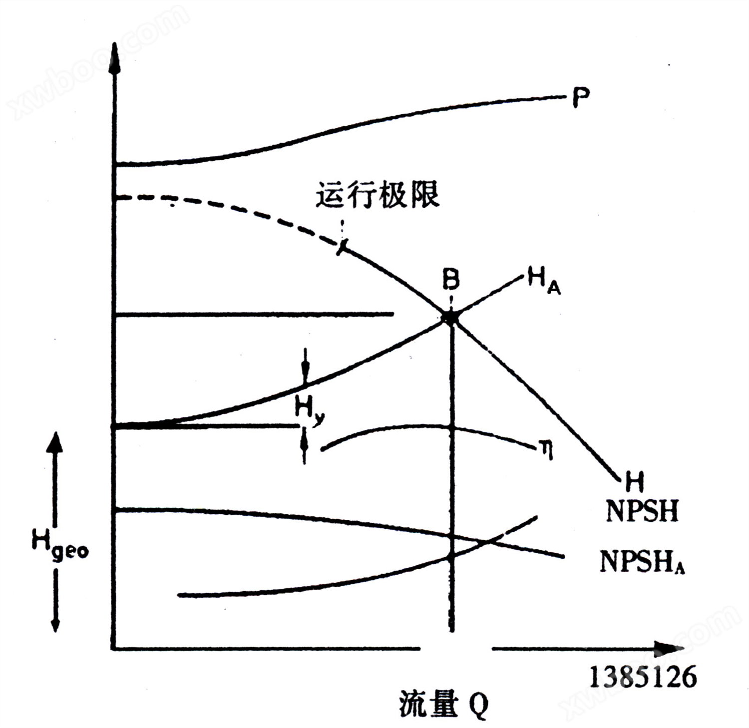
P - Power
H - Total head, efficiency
NPSH - cavitation allowance
Many operational failures of pumps are usually caused by hydraulic reasons. The hydraulic characteristics of a pump are represented by its characteristic curves H, P, η, and NPSH, as well as the device characteristic curves HA and NPSHA. The operating point B is the intersection of the device characteristic curve HA and the pump characteristic curve H.
If the cause of the malfunction cannot be determined, please contact the manufacturer.
Special reminder: Please do not disassemble the water pump without the manufacturer's consent. Otherwise, the manufacturer may be exempted from after-sales responsibility.
2) Fault List:
| Fault | Cause of occurrence |
| Pump pressure too low | 1,3,5,6,7,8,9,21,26,27,28,29,32,35 |
| Pump pressure too high | 1,13 |
| The flow is too high | 1,13 |
| Traffic is too low | 1,3,5,6,7,8,9,21,26,27,28,29,32,35 |
| Excessive power consumption | 1,7,11,13,34 |
| The pump does not produce water after starting | 1,2,3,4,5,6,9,29,32 |
| Pump stops pumping water | 3,4,5,6,9,26,29,32 |
| Unstable pump operation (noise, vibration) | 1,3,4,5,8,9,13,17,18,22,23,24,26,28,29,3031,32,33,34,35 |
| Unacceptable increase in pump casing temperature | 1,3,12,16,24,34 |
| The bearing temperature is too high | 17,18,19,20,22,23,31,34 |
| Excessive leakage of shaft seal | 12,15,22,23,25,33 |
| MOTOR OVERLOAD | 10, 11, 21 |
| Pump leakage | 14 |
3) Exclude
| 1. Scenario B is not a design point | - Increase import pressure |
| - Adjust the operating point again | - Increase suction pressure through throttling |
| 2. The gas in the pump or pipeline is not completely discharged or there is insufficient water filling in the pump | - Reduce the installation height of the pump |
| - Exhaust | If the pipeline loss is too large, change the inlet pipeline |
| - Install exhaust valve | 6. Air enters the shaft seal |
| 3. Blockage of inlet pipeline or impeller | - Clean the sealed pipeline, if possible, introduce sealing fluid from the outside or increase pressure |
| - Clean the impeller | - Replace the packing material |
| - Check for impurities in the equipment | - Check the liquid level of the water supply tank |
| - Clean the blockages in the pump and pipelines | - Replace the shaft seal |
| - Check the filter screen and inlet diameter | - Replace the pad |
| 4. Bubbles form in the pipeline | - Replace the shaft sleeve |
| - Improve import regulations | 7. Turn in the opposite direction |
| Adjust the pipeline layout | - Change the power two-phase connector |
| - Install exhaust valve | - Check the circuit connections |
| 5. The suction range is too high (effective NPSH is too low) | - Check the position of the impeller and correct it if necessary |
| - Improve import conditions | |
| 8. The speed is too low | - Clean the sealed pipeline, if possible, use an external water source or increase pressure for the sealing fluid |
| - Increase speed 1) | - Replace the shaft seal |
| - Replace the faulty fuse | - Replace worn parts |
| - Check if there is poor contact in the circuit connection | - Replace the shaft sleeve |
| - Check the distribution box | 16. Insufficient coolant or contaminated cooling chamber |
| - Install a larger impeller 1) | - Check the pressure of flushing and sealing fluid |
| 9. Internal wear and tear | - Clean the sealed pipeline, if possible, use an external water source or increase pressure for the sealing fluid |
| - Check the operating points and adjust them | - Increase coolant flow rate |
| - Increase suction pressure through throttling | - Clean the coolant |
| - Check the chemical impurities and solid content in the medium | 17. The crew did not align well |
| - Replace worn parts | - Adjust the pump and motor again |
| 10. The suction pressure of the pump is lower than the contract requirement | - Check the pipeline connections and pump installation, and reduce pipeline devices if necessary |
| - Adjust the operating point again | 18. Improper adjustment of the pump may cause resonance in the pipeline |
| - Increase suction pressure through throttling | - Re adjust |
| 11. The specific gravity or viscosity of the transported liquid exceeds the contract specifications | - Check the pipeline connections and pump installation, and reduce pipeline layout if necessary |
| - Reduce the speed | - The pipeline is connected with shock-absorbing materials |
| If there is a fixed overload, if possible, cut the impeller | 19. Excessive axial force 1) |
| 12. The packing gland, end cap, and sealing gland are installed incorrectly, and the packing material is incorrect | - Check the operating points and adjust them |
| - Adjustment | - Check the operating status |
| - Replace | - Check the suction flow rate |
| - Correction | 20. Too little lubricating oil, too much or not suitable |
| - Replace the packing material | - Clean up |
| - Replace worn parts | - Replace |
| 13. The speed is too high | - Increase, decrease or replace lubricating oil |
| - Reduce the speed | 21. Two phase operation |
| If there is a fixed overload, it is possible to cut the impeller | - Replace the faulty fuse |
| 14. Loose bolt connection/improper sealing | - Check the circuit connections |
| - Check | - Check the distribution box |
| - Tighten the bolts | 22. Unbalanced rotor |
| - Replace the pad | - Clean the rotor |
| - Check the pipeline connections and pump installation, and reduce pipeline layout if necessary | - Rebalance of rotor |
| 15. Wear of shaft seal | |
| - Check the pressure of the punching and sealing fluid | |
| 23. Bearing damage | - Increase import pressure |
| - Replace | - Check the airtightness of the imported pipeline and if necessary, tighten the sealing gasket |
| 24. Low traffic | - Replace defective pipelines |
| - Adjust the operating point again | 30. Cavitation (abnormal sound) |
| - Increase speed 1) | - Improve import conditions |
| Fully open the shut-off valve in the inlet pipeline | - Check the operating status |
| Fully open the shut-off valve in the water outlet pipeline | - Increase import pressure |
| - Recalculate the hydraulic loss H1 measured by Dai | - Reduce the installation height of the water pump |
| 25. There is a vortex at the inlet | 31. Insufficient rigidity of the foundation |
| - Check the pressure of the flushing fluid and sealing fluid | - Renovation |
| Clean the sealed pipeline, and if possible, use an external water source or increase pressure for the sealing fluid | - Check |
| 26. The water level has dropped too much | - Correction |
| - Check the operating status | 32. Parallel operation not allowed |
| - Raise the minimum water level | - Adjust the operating conditions to new ones |
| - Increase import pressure | - Change the pump and head Hl) |
| - Increase suction pressure through throttling | 33. Incorrect bearings |
| - Change the pump head H1) | One replacement |
| 27. The pump cannot use triangular wiring | 34. The impeller collides with the pump casing |
| - Check the connection of the circuit | - Adjustment |
| - Check the distribution box | - Check the rotor and balance device |
| 28. Bubbles that are not allowed to exist in the medium | - Check the position of the impeller and adjust it if necessary |
| - Exhaust | - Check the pipeline connection to ensure that the pump is not under stress |
| - Check the airtightness of the imported pipeline and if necessary, tighten it | 35. Inappropriate flow rate of pump inlet pipe |
| Sealing pad | - Change the pipeline |
| - Install exhaust valve | If the negative force in the pipeline is too high, if necessary, change the inlet pipeline |
| 29. Air enters the pump inlet | - Check if the pipeline is twisted or deformed (such as where the pipe bends) and correct it |
| - Change import conditions | |
| - Raise the low water level | |
| - Change the water level |
Note: 1) Please consult our factory for the bidding documents
This manual reserves the right to make partial changes due to technological advancements!