-
E-mail
285555402@qq.com
-
Phone
18520508508
-
Address
Building 19, Donghu High tech Industrial Innovation Base, No. 9 Miaoshan Avenue, Miaoshan Development Zone, Jiangxia District, Wuhan City, Hubei Province
Product Categories
Hubei Nankong Instrument Technology Co., Ltd

Multi variable vortex flowmeter
NegotiableUpdate on 03/30
- Model
- Nature of the Manufacturer
- Producers
- Product Category
- Place of Origin
Overview
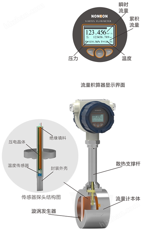
The LUGK multivariable vortex flowmeter incorporates a temperature sensor into the vortex flowmeter and uses the flow sensor sleeve as the temperature sleeve to isolate the vortex flow and temperature sensor from the process, ensuring easy calibration and replacement.
Product Details
LugkMulti variable vortex flowmeterfeature
Install a temperature sensor in the vortex flowmeter and use the flow sensor sleeve as the temperature sleeve to isolate the vortex flow and temperature sensor from the process, ensuring easy calibration and replacement.
The temperature compensation capability of saturated steam, which calculates density through process temperature and provides temperature compensated mass flow rate using the calculated density.
Improving performance in saturated steam, as electronic components compensate for changes in process temperature, thus enhancing performance in saturated steam.
Reduce installation costs, multivariable vortex flowmeter does not require external temperature sensors.
Equipped with a flow integrator to provide additional functionality, integrating a multivariable vortex flowmeter with a pressure transmitter can achieve full pressure and temperature compensation for superheated steam and various gases.
LUGKMulti variable vortex flowmeterWorking principle and structure
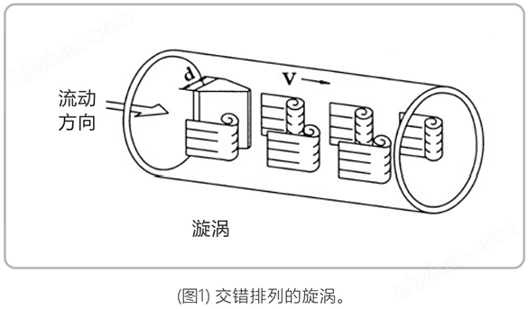
(1) The mass vortex flowmeter is a fluid oscillating flow meter made based on the principle of "Karman vortex street". When a non flow energy type cylinder is inserted into the flowing fluid, two columns of staggered vortices will be generated at the rear of the cylinder.
The vortex separation frequency f is directly proportional to the measured flow velocity V of the column and inversely proportional to the width d of the column:
Formula (1) for f=Stxv/d
St is a dimensionless constant that can be determined experimentally. When the geometric shape and size of the vortex generating body are designed properly, the St number is a constant over a wide range of Reynolds numbers, as shown in Figure 1.
Re=VxD/u formula (2)
The kinematic viscosity of fluid U
Diameter of D flowmeter
(2) Flow meter structure diagram: (Figure 2)