-
E-mail
1297746754@qq.com
-
Phone
18321779705
-
Address
Jinze Industrial Park, Qingpu District, Shanghai
Product Categories
- Multi-stage centrifugal pump | vertical centrifugal pump
- Sewage self-priming pump
- Pipeline centrifugal pump | Vertical pipeline pump
- Single-stage centrifugal pump | pipeline centrifugal pump
- Stainless steel self-priming pump | self-priming water pump
- Vertical multi-stage pump | multi-stage pipeline pump
- Stainless steel multi-stage pump | corrosion-resistant multi-stage pump
Shanghai Zhongqiu Pump Industry Co., Ltd

Vertical multi-stage fire hydrant pump
NegotiableUpdate on 05/24
- Model
- Nature of the Manufacturer
- Producers
- Product Category
- Place of Origin
Overview
The 80DL vertical multi-stage fire hydrant pump adopts a vertical segmented structure, which has the advantages of smooth operation, low noise, long service life, small footprint, and easy installation and maintenance. It adopts an excellent high-efficiency and energy-saving hydraulic model in China, with high efficiency, smooth performance curve, wide operating range, in accordance with the relevant regulations of the fire department, and can meet the needs of different users. It is used for conveying media that do not contain hard particles and physical and chemical alternatives similar to water.
Product Details
Overview of 80DL vertical multi-stage fire hydrant pump:
The 80DL vertical multi-stage fire hydrant pump adopts a vertical segmented structure, which has the advantages of smooth operation, low noise, long service life, small footprint, and easy installation and maintenance. The 80DL vertical multi-stage fire hydrant pump adopts an excellent domestic high-efficiency and energy-saving hydraulic model, with high efficiency, smooth performance curve, wide operating range, in compliance with relevant regulations of the fire department, and can meet the needs of different users
The 80DL vertical multi-stage fire hydrant pump is used for conveying media that do not contain hard particles and have undergone physical and chemical transformations similar to water.
80DL vertical multi-stage fire hydrant pump, also known as 80DL vertical multi-stage fire hydrant pump, 80DL vertical multi-stage fire hydrant pump, 80DL vertical multi-stage fire hydrant pump, etc; Mainly used for high-rise building domestic water supply, fire constant pressure water supply, automatic sprinkler water supply, automatic water curtain water supply, etc., it can also be applied to factory and mine water supply and drainage, long-distance water delivery, various equipment matching use, and various production process water supply.
Schematic diagram of the structure of the 80DL vertical multi-stage fire hydrant pump:
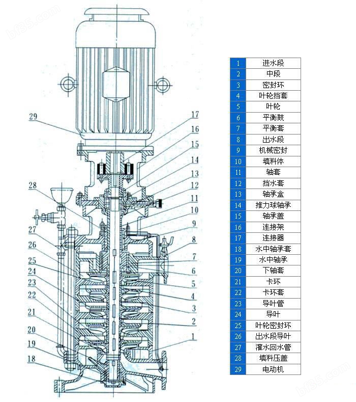
1 Inlet section 16 Connection frame
2 middle section 17 connector
3 sealing rings 18 underwater bearing sleeves
4 impeller sleeve 19 water bearing
5 impellers and 20 lower shaft sleeves
6 Balance drums 21 Clamping rings
7 Balance sleeve and 22 Snap ring sleeve
8 outlet section 23 guide vane pipe
9 Mechanical seals 24 Guide vanes
10 packing bodies 25 impeller sealing rings
11 shaft sleeve 26 outlet guide vane
12 water blocking sleeves 27 water filling and return pipes
13 Bearing Box 28 Packing Cover
14 thrust ball bearings 29 electric motors
15 bearing cover
The 80DL vertical multi-stage fire hydrant pump consists of a motor and a pump. The motor is a Y-shaped three-phase asynchronous motor, and the pump and motor are connected by a coupling. The overall connection is rigid and does not require calibration during use. The 80DL vertical multi-stage fire hydrant pump consists of a stator and a rotor. The stator part of the pump consists of components such as the inlet section, middle section, diffuser, outlet section, and packing box. To prevent stator wear, the stator is equipped with sealing rings, balance sleeves, etc., which can be replaced with spare parts after wear. The rotor part consists of a shaft, a middle wheel, a flat drum, etc. The lower end of the rotor is a water lubricated bearing, and the upper part is an angular contact ball bearing. The axial direction of the pump is mostly borne by the balance drum, and the remaining small residual axial force is borne by the angular contact ball bearing. The joint surface between the inlet and outlet sections is sealed by sealing with a paper pad. The shaft seal adopts packing or mechanical seal, and users can choose according to their needs.
The rotation direction of the pump is counterclockwise when viewed from the drive end downwards.
Performance parameters of 80DL vertical multi-stage fire hydrant pump:
The 80DL vertical multi-stage fire hydrant pump of the same series and its performance parameters are as follows:
The performance parameters of the 80DL vertical multi-stage fire hydrant pump are as follows:
Model level
Numerical caliber
(mm) Flow rate
(m3/h) Head
(m) Power
(KW) speed
(r/min) Cavitation allowance
(m)
80 DL 50-20x228050401114802.2
The performance parameters of the 80DL50-20x3 vertical multi-stage pipeline booster pump are as follows:
Model level
Numerical caliber
(mm) Flow rate
(m3/h) Head
(m) Power
(KW) speed
(r/min) Cavitation allowance
(m)
80 DL 50-20x328050601514802.2
The performance parameters of the 80DL50-20x4 vertical multi-stage pipeline booster pump are as follows:
Model level
Numerical caliber
(mm) Flow rate
(m3/h) Head
(m) Power
(KW) speed
(r/min) Cavitation allowance
(m)
80 DL 50-20x448050802214802.2
The performance parameters of the 80DL50-20x5 vertical multi-stage pipeline booster pump are as follows:
Model level
Numerical caliber
(mm) Flow rate
(m3/h) Head
(m) Power
(KW) speed
(r/min) Cavitation allowance
(m)
80 DL 50-20x5580501003014802.2
The performance parameters of the 80DL50-20x6 vertical multi-stage pipeline booster pump are as follows:
Model level
Numerical caliber
(mm) Flow rate
(m3/h) Head
(m) Power
(KW) speed
(r/min) Cavitation allowance
(m)
80 DL 50-20x6280501203014802.2
The performance parameters of the 80DL50-20x7 vertical multi-stage pipeline booster pump are as follows:
Model level
Numerical caliber
(mm) Flow rate
(m3/h) Head
(m) Power
(KW) speed
(r/min) Cavitation allowance
(m)
80 DL 50-20x7780501403714802.2
The performance parameters of the 80DL50-20x8 vertical multi-stage pipeline booster pump are as follows:
Model level
Numerical caliber
(mm) Flow rate
(m3/h) Head
(m) Power
(KW) speed
(r/min) Cavitation allowance
(m)
80 DL 50-20x8880501604514802.2
The performance parameters of the 80DL50-20x9 vertical multi-stage pipeline booster pump are as follows:
Model level
Numerical caliber
(mm) Flow rate
(m3/h) Head
(m) Power
(KW) speed
(r/min) Cavitation allowance
(m)
80 DL 50-20x9980501804514802.2
The performance parameters of the 80DL50-20x10 vertical multi-stage pipeline booster pump are as follows:
Model level
Numerical caliber
(mm) Flow rate
(m3/h) Head
(m) Power
(KW) speed
(r/min) Cavitation allowance
(m)
80 DL 50-20x101080502005514802.2
Installation dimension diagram of 80DL vertical multi-stage pipeline booster pump:
Model level
数 HhH1H2LBXBbxbn-∮d
80 XBD-DL 50-2021515
60
150277
280
450x450
400x400
4-24
31649366
41865455
52030544
62120633
72270722
82385811
92475900
10//
Fault and maintenance of 80DL vertical multi-stage pipeline booster pump:
Possible causes and solutions for the formation phenomenon
The water pump does not absorb water, and the pressure gauge and vacuum gauge pointers jump violently. 1. Insufficient injection and water intake
2. Leakage at the connection between the pipeline and the instrument
3. Excessive suction. 1. Check if the bottom valve is leaking water Hire enough water again
2. Tighten the leaking area
3. Reduce the water absorption height
The water pump does not absorb water, and the vacuum gauge indicates high vacuum. 1. The bottom valve is not open or has been blocked
2. The resistance of the suction pipe is too high
3. Filter blockage 1. Check the bottom valve
2. Replace the water absorbent
3. Clean the filter
The pressure gauge has pressure but still does not produce water. 1. The resistance of the outlet pipe is too high
2. Incorrect rotation direction
3. The outlet pipe valve is not open
4. Impeller blockage 1. Check or seal short water pipes
2. Check the motor Two phase intermodulation
3. Open the outlet valve
4. Remove the dirt inside the impeller
Unable to achieve the designed flow rate. 1. There is air intake
2. Due to the decrease in water level Insufficient submergence depth,
3. There are foreign objects blocking the impeller
4. Severe wear on the rotor part. 1. Check and eliminate the leaking parts
2. Extend the suction pipe Deepen the submergence depth
3. Disassemble and remove foreign objects
4. Replace the damaged seal
The pump consumes too much power. 1. The packing pressure is too tight And generate heat
2. Excessive flow
3. There is collision between the rotating body and the shell
4. Wear of pump bearings
5. Pump shaft bending 1. Relax appropriately
2. Reduce the opening of the gate valve
3. Repair
4. Replace the bearings
5. Replace or calibrate
Pump vibration increases 1. Local blockage of impeller
2. Impeller damage
3. Insufficient traffic
4. The pump shaft is not concentric with the motor
5. Bearing damage
6. Mixing with air Cavitation occurs 1. Disassemble and remove foreign objects
2. Replace
3. Slightly open the outlet valve
4. Fixed point alignment
5. Replacement
6. Change the inhalation position Improve the suction pipe
Similar Product Recommend


