-
E-mail
MKT@srodcn.com
-
Phone
18926498215
-
Address
1101, Building 2, Yinxing Zhijie Phase 1, No. 1301 Guangguan Road, Longhua District, Shenzhen
Product Categories
Shenzhen Schroder Industrial Group Co., Ltd


Belt inspection robot
NegotiableUpdate on 02/24
- Model
- Nature of the Manufacturer
- Producers
- Product Category
- Place of Origin
Overview
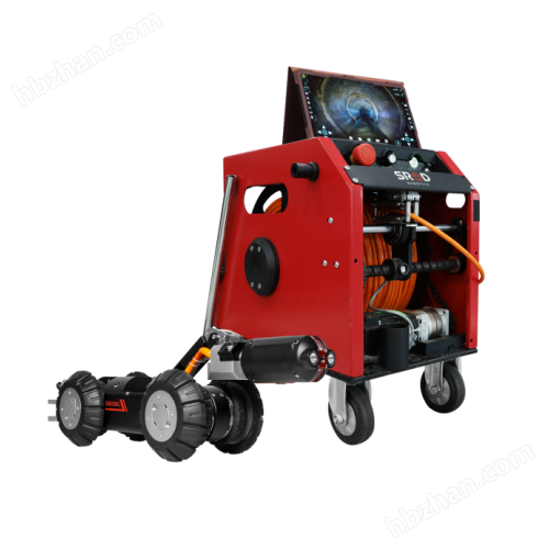
The belt inspection robot is mainly composed of a pipe conveyor inspection host, roadbed track, various sensors, management platform, and other auxiliary equipment. Support 24/7 online real-time monitoring, with various data transmitted to the management platform through wireless networks. The system filters and analyzes the data and reports the results to on-site maintenance personnel; At the same time, the data results are stored locally as the data foundation for later system optimization learning.
Product Details
Belt inspection robotIt mainly consists of a pipe conveyor inspection host, roadbed track, various sensors, management platform, and other auxiliary equipment. Support 24/7 online real-time monitoring, with various data transmitted to the management platform through wireless networks. The system filters and analyzes the data and reports the results to on-site maintenance personnel; At the same time, the data results are stored locally as the data foundation for later system optimization learning. Real time alarm and early warning of faults such as damaged conveyor belt rollers, edge damage, abnormal noise collection, and equipment abnormalities are achieved through main technical means such as image recognition, infrared temperature measurement, temperature vibration monitoring, and smoke monitoring.
Belt inspection robotmanagement platform
Utilizing a software platform to achieve remote control of robots, the software platform is installed in the remote control station of the ground control room. At the same time, the software platform can intuitively reflect the video information and various parameters collected by the inspection robot. For robot inspection systems in complex scenarios, the backend can centrally and uniformly schedule multiple robots, fully leveraging system flexibility and improving overall efficiency.
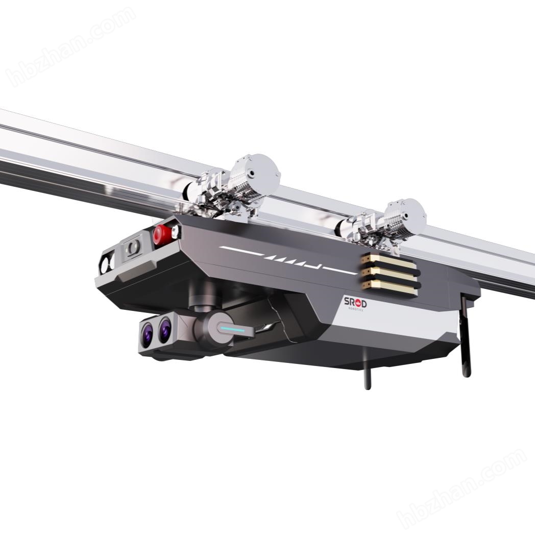
The inspection robot can replace the inspectors to complete the daily inspection tasks of the equipment at a fixed time, at a fixed point and in high quality. The robot body is suspended on the track and runs back and forth in the inspection area, simulating the inspectors to walk in the inspection area. The inspection robot is equipped with a variety of sensors to collect the image, sound, infrared thermal image, temperature data, smoke, multiple gas concentration parameters and other information at the inspection site in real time. It not only simulates the "image acquisition, sound acquisition, infrared temperature detection, Internet connection" during the inspection work of the inspectors, but also classifies and stores the traditional artificial sensory phenomena that cannot be reproduced and recorded accurately quantified, using digital images, sounds and accurate data in real time, so as to facilitate the query and reproduction of fault problems. On the basis of completing the daily inspection tasks of inspection workers, the inspection robot has added powerful intelligent big data analysis functions. It uses intelligent perception key technology algorithms to deeply process the collected digital information, comprehensively analyze and accurately judge the current operating status of the equipment, and based on big data analysis warning technology, predict and warn enterprise equipment operation faults in advance.
1. Remote video surveillance function machine
The human body is equipped with a high-definition camera and has low light imaging function. During the inspection process, video surveillance is conducted on rollers, belts, etc. The system can simultaneously record visible light videos, infrared thermal imaging videos, and audio information for real-time viewing by centralized control personnel. When an unexpected situation occurs on site, the centralized control personnel can control the robot to quickly arrive at the scene and check the abnormal situation as soon as possible.
2. Monitoring function for damaged conveyor belt rollers
The inspection robot is equipped with a high-definition camera and a high-precision infrared thermal imaging thermometer. During the inspection process, the inclined and flat rollers are positioned and temperature measured separately. When the temperature rise of the rollers reaches a certain threshold, the system sends out an alarm message. Due to the significant differences in operating conditions and temperature levels among different sites, the inspection strategy adopts relative temperature as the basis for judgment, effectively reducing misjudgments caused by external factors such as environmental factors and equipment accuracy
3. The environmental safety monitoring function inspection robot is equipped with a smoke sensor, which can detect the smoke environment information and over limit alarm function in the surrounding working conditions in real time during the inspection process. It can monitor the environmental safety inside the belt corridor bridge, and the detection standards should meet relevant requirements. The detection data and location should be uploaded to the robot monitoring background in real time and fed back to the staff in the monitoring room.
4. By using a fixed-point high-definition visible light camera, the image of the belt edge can be captured clearly. Through image recognition technology, abnormal situations such as damage and cracks on the belt edge can be automatically identified. Real time detection and reporting of abnormal states of the belt through high-precision sensors and intelligent algorithms.
5. The use of a fixed-point intelligent camera can monitor and analyze belt deviation, and the recognition of belt deviation is shown in the following figure. Belt deviation monitoring display window (customized display according to project site needs)
6. The belt tear detection module is deployed below the belt, using laser to horizontally irradiate the bottom surface of the belt. The high-speed industrial camera captures the real-time image of the laser beam irradiation area, and the flexible light source supplements the light. The visual detection algorithm intelligently analyzes and calculates to detect the degree of belt tear and deviation. After the deployment and debugging of the equipment and software are completed, continuous image recognition is carried out 24/7. When abnormal features on the surface of the belt are detected, the system automatically alarms and records screenshots, which are also recorded in the belt abnormality record table of the database for subsequent queries. The system uses laser stripes to continuously scan the surface and intelligently determine whether the belt has longitudinal tearing. Once longitudinal tearing occurs, an alarm is immediately issued and the belt is stopped. The system can replace manual detection, achieve all-weather automatic detection, timely detection and shutdown of longitudinal tearing faults of conveyor belts, and minimize losses. Belt tear monitoring display window (customized display according to project site requirements)
7. The material flow detector can monitor the material flow through it in real time, including the flow size and direction, and feed back this information to the control system. Through linkage with the control system, precise control of material flow can be achieved, such as adjusting the conveying speed and direction of materials.
8. The high-definition camera equipped on the robot can clearly capture images of the ground below and around the conveyor belt. Through algorithms such as image recognition and edge detection, the images captured by the camera are processed to identify the scattering area on the ground. These algorithms can distinguish materials from ground backgrounds and calculate the area and distribution of materials. When the ground scattering exceeds the preset threshold, the system will automatically trigger an alarm mechanism to notify the staff to handle it. Schematic diagram of ground scattering monitoring
9. The monitoring function system for material blockage at the discharge port relies on visual algorithms for state analysis and detection, with accurate recognition accuracy; Monitoring components can be quickly replaced and deployed, with a unified quick release interface; Adopting fixed-point installation and screw fixation, it can be quickly assembled on site without welding; Distributed monitoring devices can display the approximate location of the device on the electronic map of the USR client; The USR client has functions such as deployment, display, abnormal alarm, and monitoring logs, and the APP can receive corresponding risk warning notifications; The local server can output passive node signals for belt linkage control.
10. The abnormal noise collection and detection function of the conveyor belt mainly includes the collection and analysis of sound signals, as well as the identification and warning of abnormal situations. Through the microphone installed on the robot body, the system can capture the sound changes during the operation of the belt in real time, in order to identify abnormal situations such as roller noise, belt slippage, tearing, etc. 11. Abnormal monitoring function of transmission equipment. Transmission equipment is the core equipment of conveyor belts, mainly including drive motors, reducers, head and tail rollers, reversing rollers, etc. Generally, each device needs to be equipped with 2 vibration sensors. The detection principle is mainly to collect the vibration values of the bearing positions during the operation of each device and draw the frequency spectrum status, classify and compare them with the database model, and obtain fault information for alarm or warning. Real time collection of temperature and vibration data of various detection objects using temperature and vibration sensors, and drawing of dynamic change curve graphs. The data is converted into Ethernet data through a serial server, which serves as the data source for the upper computer management software to judge the operation status of the equipment.
12. The autonomous inspection and remote control function inspection robot can autonomously determine whether the conveyor belt is running. When the conveyor belt starts running and reaches a stable state, the inspection robot automatically starts back and forth inspection, and can choose different inspection strategies according to actual needs. When an emergency malfunction occurs on site or a temporary inspection is required at certain locations, the manual inspection mode can be activated. Users can use the PC management platform to remotely control the robot, including forward, backward, stop, and speed modification, so that the robot can arrive at the temporary site for inspection. Robot control mode (switching between manual control and automatic inspection)
13. The autonomous obstacle avoidance function robot has a safety obstacle avoidance function. When encountering obstacles or personnel, it will automatically stop and issue an alarm. After the personnel or obstacles are removed, it will automatically continue the current action task.
14. Robot self checking function: As the main body of the inspection system, the robot is equipped with main detection equipment to collect various data information at the front end. In order to ensure the daily operation of the robot, it will perform self inspection before starting the inspection. The self inspection content includes infrared thermal imaging, high-definition camera, motor, pan tilt zoom, internal storage, and various sensors. If any component abnormalities are found, an abnormal status indication will be given and the system abnormality information will be uploaded to the monitoring background, which facilitates the timely detection of faults by operation and maintenance personnel, reduces processing time, and improves the efficiency of fault resolution.
15. The fault location positioning function inspection robot is equipped with an odometer, and a magnetic locator is fixed along the track for global auxiliary positioning calibration. The inspection robot can quickly locate the fault point through a pre-set magnetic locator and mileage system, and transmit real-time warning information to on-site staff for processing. At the same time, the odometer information can be corrected in real time, and the current position information of the inspection robot can be uploaded in real time. During the early stage of construction deployment and map building, the roller frame should be numbered as needed. -17- This number corresponds to the marked point on the map, and maintenance personnel can find the fault point for repair based on the alarm content and number.
16. The fault analysis and warning function robot will collect temperature data of all rollers throughout the inspection process and transmit the data to the management platform. The platform analyzes, filters, and draws recent temperature change curves to determine the trend of roller health status. At the same time, the system supports exporting status reports to provide reference for equipment operation and maintenance departments.
17. The autonomous charging function of the inspection robot monitors the battery level and the distance between the current location and the charging station in real time. Based on the autonomous recharging strategy, the inspection robot autonomously navigates to the dock charging station and automatically starts charging. The robot adopts a contact charging station with a charging time of about 2 hours. When the robot completes inspection or needs to be charged due to low battery, it will trigger the in place switch when returning to the charging station. After confirming the position, it will send a signal to the system to start charging, and the charging station will immediately start charging; After the robot is fully charged, it will send a signal to the charging station to stop charging. Appearance diagram of robot dock and dust removal device (customized according to the on-site space)
18. The inspection robot has an autonomous dust removal function and operates in a dusty environment on the conveyor belt. The robot device meets the IP66 waterproof and dustproof rating, but dust may adhere to the surface of the camera and thermal imaging camera, causing interference with image recognition and temperature measurement. Therefore, a complete dust removal device is deployed outside the dock station. Before entering the dock station, the robot activates the overall dust removal function to remove dust from key parts of the robot. After the dust removal is completed, it enters the dock station for charging and parking.
19. The operation and maintenance inspection data analysis and query function data analysis interface is divided into equipment alarm records, robot body alarm information, statistical data, equipment alarm statistics, and other parts. Historical queries include two major modules: report queries and historical task result queries. Report query provides a query of the historical results of all measurement points inspected by the robot within a certain period of time, and supports exporting Excel or PDF reports. The query of historical task results can be classified by task, and the inspection results of historical tasks can be viewed. In the results -18-, the information of the inspected measuring points in this task and the historical record information of the measuring points, including visible light shooting images, infrared images, etc., are included.
20. The real-time map function of the robot's backend map module displays real-time map information of the robot, including map paths, RFID positions, robot inspection point positions, and real-time robot positions. The map supports manual zooming, drag and drop movement, full screen display, and element hiding operations.
21. The alarm display function robot analyzes the monitored data results and can display alarms for indicators that exceed the limit, such as excessively high temperature and environmental information indicators. It can also alert for its own abnormalities, helping operations personnel quickly locate problems and facilitating operations.
22. The video, photo, and data generated during the inspection of data storage function shall be saved for no less than one month, and automatic redundant backup function of inspection data shall be provided, supporting real-time viewing of monitoring videos. Provide inspection data export function to ensure long-term preservation of historical data.
23. System log function: The robot backend system supports log recording function, which can record user login, parameter settings, robot operations and other behaviors, facilitating later operation and maintenance management.
24. The voice intercom function robot body should carry a voice intercom module, and the staff can have real-time conversations with the site through the voice intercom switch in the background. The on-site staff do not need to perform unnecessary operations and can respond in real time next to the robot.
25. The data integration and analysis function of the distributed monitoring system achieves centralized management and control of multiple monitoring systems by building a comprehensive management platform, improving overall operational efficiency and security. The system provides standard data interfaces to facilitate data integration and sharing with other systems such as fire alarm systems, transportation control systems, etc.
Similar Product Recommend