-
E-mail
yilifm@163.com ,9715905@qq.com
-
Phone
13868807962
-
Address
Yili Valve Industrial Park, Wuxing Industrial Park, Oubei New District, Yongjia County, Wenzhou City, Zhejiang Province
Product Categories
Zhejiang Yili Valve Co., Ltd
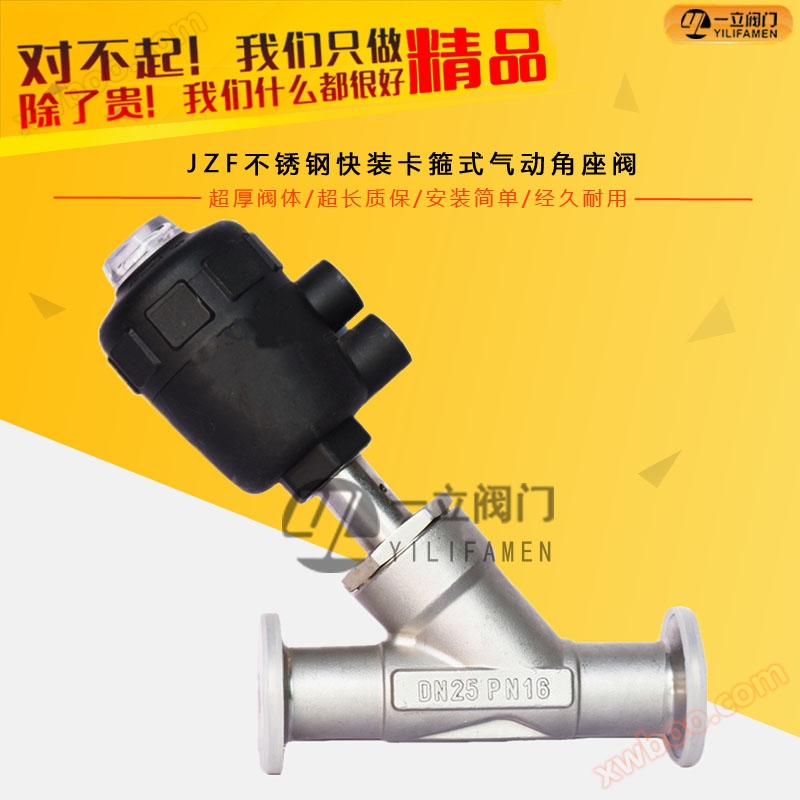
JZF Stainless Steel Quick Install Clamp Pneumatic Angle Seat Valve
NegotiableUpdate on 04/06
- Model
- Nature of the Manufacturer
- Producers
- Product Category
- Place of Origin
Overview
1. Pneumatic angle seat valves can be divided into single acting and double acting single acting according to the cylinder (the pneumatic head is usually a hole); working principle; According to the function of spring reset to achieve opening and closing, it is divided into normally open and normally closed types. Double acting (pneumatic head usually has two holes)
Product Details
Working Principle:
In non working state, the valve is normally open or closed due to the action of the spring. When the actuator piston is acted upon by compressed gas, the valve opens or closes, and the double acting form relies on compressed gas to control the valve opening and closing.
Connection size:

Pneumatic angle seat valves can be divided into:
Single acting and double acting single acting (pneumatic head usually has one hole); working principle; According to the function of spring reset to achieve opening and closing, it is divided into normally open and normally closed types.
Double acting (pneumatic head usually has two holes); Working principle: Control its switch by supplying air.
Pressure range: 0-1.6Mpa
Medium temperature: -10 ℃~+180 ℃
Environmental temperature: -10 ℃~+60 ℃
Valve body material: stainless steel
Sealing material: polytetrafluoroethylene
Actuator housing: polyimide, stainless steel
Application of Pneumatic Angle Seat Valve in Daily Life:
Control gas: neutral gas, air
Control liquids: automation industrial control fluids, food grade dairy industry, domestic water, ordinary pipeline fluid media, etc.
Application scope:
① Beer and drinks filling machinery;
② Textile printing&dyeing;
③ Gas industry/gas industry;
④,制药及医疗设备/ pharmacy & medical equipment;
⑤ Chemical industry/chemical industry;
⑥ High temperature sterilization/disinfection;
⑦ Foam machinery/rolling equipment;
⑧ Water pollution treatment/water sewage disposal.
Working principle of angle valve:
In non working state, the valve is normally open or closed due to the action of the spring. When the actuator piston is compressed by gas, the valve opens or closes, and the double acting form relies on compressed gas to control the valve opening and closing
Installation environment:
① Control form: direct acting;
② Pipeline pressure: MAX 1.6MPA (232psi);
③ Control pressure: 0.3-0.8MPA (43.5-116psi);
④ Structure: Angular
⑤ Interface: DN10-DN100;
⑥ Medium viscosity: 600mm2/S;
⑦ Medium temperature: -10 ° C to+180 ° C (PTFE);
⑧ Environmental temperature: -10 degrees to+60 degrees;
⑨ Installation location: Any position (360 degree optional installation).
Installation and disassembly:
① Connect the valve to the pipeline, ensuring that the arrow attached to the valve body is consistent with the direction of the fluid (the arrow on the outside of the valve body represents the direction of fluid flow, please follow the installation instructions);
② Welding installation: Please remove the actuator during welding;
③ Threaded, flange, quick installation: can be installed normally;
④ Disassembly: Before disassembling, ensure that the air pressure on the valve has been released; Light unloading; Protect the threads and sealing materials after disassembly;
⑤ The connection between the valve body and the pipeline requires sufficient torque force. The torque values for each dimension are as follows: DN15 is 40Nm, DN20 is 50Nm, DN25 is 70Nm, DN32 is 150Nm, DN40 is 150Nm, DN50 is 170Nm, DN80 is 240Nm, and DN100 is 300Nm.
⑥ When installing, please ensure that there are no residues inside the pipeline and at the interface.
⑦ After installation, the inspection and connection points must be sealed and free of leaks before use.
Similar Product Recommend


