-
E-mail
sales@shyuhu.com
- Phone
-
Address
No. 6898 Linhai Road, Qinggang Industrial Park, Fengxian District, Shanghai
Product Categories
Shanghai Yuhu Self Control Valve Co., Ltd

Q347F/H worm gear fixed ball valve
NegotiableUpdate on 04/07
- Model
- Nature of the Manufacturer
- Producers
- Product Category
- Place of Origin
Overview
Q347F/H Worm Gear Fixed Ball Valve Worm Gear Fixed Ball Valve (Structural Dimensional Drawing) I. Overview of Worm Gear Fixed Ball Valve Products Shanghai Yuhu Company's Q347F/H Worm Gear Fixed Ball Valve is a new generation of high-performance ball valve, suitable for long-distance pipelines and general industrial pipelines. Its strength, safety, and resistance to harsh environments have been specially considered in the design, and it is suitable for various corrosive and non corrosive media
Product Details
Q347F/H worm gear fixed ball valve
 |
") |
|---|---|
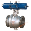
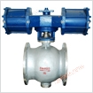
| Worm fixed ball valve | Worm fixed ball valve (structural dimension diagram) |
1、 Overview of Worm Gear Fixed Ball Valve Products
The Q347F/H worm wheel fixed ball valve from Shanghai Yuhu Company is a new generation of high-performance ball valve, suitable for long-distance pipelines and general industrial pipelines. Its strength, safety, and resistance to harsh environments have been specially considered in the design, and it is suitable for various corrosive and non corrosive media. Compared with floating ball valves, fixed ball valves transmit all the force generated by the fluid pressure in front of the valve on the ball to the bearing during operation, which does not cause the ball to move towards the valve seat. Therefore, the valve seat will not bear excessive pressure. Therefore, flange type fixed ball valves have smaller torque, smaller valve seat deformation, stable sealing performance, and longer service life, making them suitable for high-pressure and large-diameter applications. Advanced spring pre seat components with self tightening characteristics achieve upstream sealing. Each valve has two valve seats, which can seal in each direction, so there is no flow restriction during installation, and it is bi-directional.
The worm wheel fixed ball valve has two types of valve body structures: two-stage and three-stage. The middle flange is connected by bolts, and the seal is made of reinforced polytetrafluoroethylene embedded in a stainless steel ring. There is no spring at the back of the steel ring to ensure that the valve seat is tightly attached to the ball, maintaining a seal. There are no PTFE bearings on both the upper and lower valve stems, reducing friction and making operation effortless. There are no adjustment plates at the bottom of the small shaft to ensure the joint position between the ball and the sealing ring. Full bore: The valve flow aperture is consistent with the inner diameter of the pipeline for pipeline cleaning.
2、 Characteristics of Worm Gear Fixed Ball Valve Products
(1) The O-type fixed flange ball valve adopts a fixed ball design, and the relative moving parts are made of self-lubricating materials with extremely low friction coefficient, resulting in low operating torque. In addition, the long-term sealing of the sealing grease makes the operation more flexible.
(2) The valve adopts a high platform structure and ISO5211 connection standard, which can make the installation of electric/pneumatic actuators more specialized.
(3) The O-type fixed ball valve adopts a full bore or reduced diameter design, with low flow resistance.
(4) The metal hard sealed O-type fixed flange ball valve adopts a bi-directional metal movable sealing structure, with automatic compensation and self-cleaning functions, and superior sealing performance.
(5) The O-type fixed ball valve adopts a fixed ball design and adds a pre tension spring, making the ball valve have automatic pressure relief function.
(6) Each ball valve has two movable sealing seats that can seal in both directions, so there is no need to consider the flow direction of the medium during installation.
(7) Featuring a fire-resistant and anti-static structure, conductive springs are installed between the valve stem and valve body, as well as between the valve stem and ball body, to prevent static electricity from igniting flammable media. Ensure system security.
(8) The fire-resistant structure provides dual protection. In the event of a fire that burns the sealing ring, all sealing parts of the ball valve can form a metal to metal hard sealing structure.
(9) Automatic pressure relief structure, when the liquid medium trapped in the valve chamber vaporizes due to temperature increase, resulting in abnormal pressure rise in the chamber, the medium in the chamber can rely on its own thrust to push the valve seat and automatically relieve pressure, thereby ensuring valve safety.
3、 Main component materials of worm gear fixed ball valve
| 1 | valve body | WCB | A2116-WCB |
|---|---|---|---|
| 2 | spring | 60Si2aMn | AISI 9260 |
| 3 | sealing ring | PTFE | PTFE |
| 4 | shim | PTFE | PTFE |
| 5 | Discharge nut | 25 | A105 |
| 6 | 0-type sealing ring | rubber | rubber |
| 7 | bottom cover | 25 | A105 |
| 8 | screw | 35 | A193-B7 |
| 9 | fixed axis | 1Cr13 | A276-410 |
| 10 | plain bearing | PTFE& | PTFE& |
| 11 | sphere | 1C18Ni9Ti | SS304 |
| 12 | valve cover | WCB | A216-WCB |
| 13 | valve seat | 25 | A105 |
| 14 | valve stem | 1Cr33 | A276-410 |
| 15 | stud | 35CrMoA | A193-B7 |
| 16 | nut | 35 | A194-2H |
| 17 | press-fit sleeve | 25 | A105 |
| 18 | filler | PTFE | PTFE |
| 19 | support | WCB | A216-WCB |
| 20 | gland | WCB | A2116-WCB |
| 21 | Key Key | 45 | AISI C 1045 |
4、 Design Specification for Worm Gear Fixed Ball Valve
| Design Basis | National standard series | American standard series | |
|---|---|---|---|
| design standards | GB/T12237 | AP16D | ANSI B16.34 |
| Length of flange connection structure | GB/T12221 | AP16D | ANSI B16.10 |
| Structural length (welding) | GB/T15188.1 | AP16D | ANSI B16.10 |
| flange connection | GB/T9113 JB/T79 Hg20592 | ANSI B16.5、B16.47 | |
| butt welding end | GB/T12224 | ANSI B16.25 | |
| Testing and inspection | GB/T9092 | AP16D | AP1598 |
5、 Performance Specification for Worm Gear Fixed Ball Valve
| pressure rating | Test pressure (MPa) | ||
|---|---|---|---|
| Nominal pressure (PN) | Pound class | Shell Test | Sealing Test |
| 1.0 | - | 1.5 | 1.1 |
| 1.6 | - | 2.5 | 1.76 |
| 2.5 | - | 3.8 | 2.75 |
| 4.0 | - | 6.0 | 4.4 |
| 6.4 | - | 9.6 | 7.04 |
| - | 150 | 3.0 | 2.2 |
| - | 300 | 7.6 | 5.6 |
| - | 600 | 15.0 | 11.0 |
| - | 10K | 2.4 | 1.5 |
| - | 20K | 5.8 | 4.0 |
6、 Product selection of worm gear fixed ball valve
Please fill in the "Specification Book" or indicate the following content when selecting:
1. If the model has not been selected before ordering, please provide us with the following usage parameters: 1. nominal diameter, 2. fluid properties (including nominal pressure, temperature, viscosity, or acidity/alkalinity), 3. valve body and valve core materials.
2. If the design unit has already selected the product model of our company, please order directly from our business department according to the model;
3. When the application is very important or the pipeline is complex, please provide design drawings and detailed parameters as much as possible, and our experts will review and control them for you.