-
E-mail
sales@shyuhu.com
- Phone
-
Address
No. 6898 Linhai Road, Qinggang Industrial Park, Fengxian District, Shanghai
Product Categories
Shanghai Yuhu Self Control Valve Co., Ltd

ZZLP/M Self operated Flow Control Valve
NegotiableUpdate on 04/07
- Model
- Nature of the Manufacturer
- Producers
- Product Category
- Place of Origin
Overview
ZZLP/M Self Operated Flow Control Valve ZZLP/M Self Operated Flow Control Valve I. Overview of Self Operated Flow Control Valve Products Shanghai Yuhu Company's self operated flow control valve is a new type of control valve. Compared to manual control valves, its advantage is that it can automatically adjust
Product Details
ZZLP/M Self operated Flow Control Valve
 |
|---|
| ZZLP/M Self operated Flow Control Valve |
1、 Overview of Self Operated Flow Control Valve Products
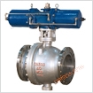
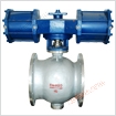
The self operated flow regulating valve of Shanghai Yuhu Company is a new type of regulating valve, which has the advantage of automatic adjustment compared to manual regulating valves. Compared to electric regulating valves, its advantage is that it does not require external power. Practical application has shown that in closed water circulation systems (such as hot water heating systems, air conditioning refrigeration systems), the correct use of this valve can easily achieve flow distribution in the system; Can achieve dynamic balance of the system; It can greatly simplify the debugging work of the system; Can stabilize the working state of the pump, etc. Therefore, self operated flow control valves have broad application prospects in heating and air conditioning engineering. The function of a self operated flow control valve is to maintain a constant flow rate through the valve when the pressure difference between the inlet and outlet of the valve changes, thereby maintaining a constant flow rate of the controlled object (such as a loop, a user, a device, etc., the same below) connected in series with it. There are many names for self operated flow control valves, such as self operated flow balance valves, constant flow valves, self balancing valves, dynamic flow balance valves, etc. Various types of self operated flow control valves have different structures but similar working principles.
2、 Main technical parameters of self operated flow regulating valve
| Nominal diameter DN | 15 | 20 | 25 | 32 | 40 | 50 | 65 | 80 | 100 | 125 | 150 | 200 | 250 | |
|---|---|---|---|---|---|---|---|---|---|---|---|---|---|---|
| Rated flow coefficient Kvs | 4 | 6.3 | 8 | 16 | 20 | 32 | 50 | 80 | 125 | 160 | 280 | 320 | 400 | |
| Maximum flow rate under effective pressure (m3/h) | 0.02MPa | 1.5 | 2.5 | 3.5 | 5.5 | 9.0 | 14 | 22 | 36 | 55 | 70 | 125 | 180 | 250 |
| 0.05 MPa | 2.5 | 3.5 | 5.5 | 9.0 | 12 | 22 | 36 | 55 | 85 | 110 | 180 | - | - | |
| Noise measurement coefficient Z value | 0.6 | 0.6 | 0.6 | 0.55 | 0.55 | 0.5 | 0.5 | 0.45 | 0.4 | 0.35 | 0.3 | 0.2 | 0.2 | |
| Allowable pressure difference | PN16 | 1.6 | 1.5 | 1.2 | 1.0 | |||||||||
| PN40 | 2.0 | |||||||||||||
| Valve cover form | Standard type -17 to+450 ℃ | |||||||||||||
| Cover type | Bolt compression type | |||||||||||||
| Sealing packing | V-shaped PTFE packing, PTFE impregnated asbestos packing, asbestos textile packing, graphite packing | |||||||||||||
| Valve core form | Single seat, sleeve type valve core | |||||||||||||
| flow characteristics | linear | |||||||||||||
3、 Technical parameters of self operated flow control valve actuator
| Effective area (cm2) | 250 | 630 |
|---|---|---|
| Throttle differential pressure (MPa) | 0.02; zero point zero five | |
| Maximum allowable pressure difference between upper and lower membrane chambers (MPa) | 0.4 | 0.15 |
| material | Film cover: galvanized steel plate; Diaphragm: EPDM or FKM sandwiching fibers | |
| Control pipelines and joints | Copper or steel pipe 10 × 1; Card sleeve connector: R1/4“ | |
4、 Main performance indicators of self operated flow regulating valve
| control accuracy | ±5% | |||
|---|---|---|---|---|
| Allowable leakage amount (Under specified experimental conditions) |
hard seal | 4 x 0.01% rated capacity of valve | ||
| Soft seal | DN15~50 | DN65~125 | DN150~250 | |
| 10 bubbles/min | 20 bubbles/min | 40 bubbles/min | ||