-
E-mail
xilunlt@126.com
-
Phone
13818833907 18939726201
-
Address
Xilun Industrial Zone, Fengxian District, Shanghai
Product Categories
Shanghai Xilun Fluid Technology Co., Ltd


5.5kw stainless steel gas-liquid mixing pump
NegotiableUpdate on 05/25
- Model
- Nature of the Manufacturer
- Producers
- Product Category
- Place of Origin
Overview
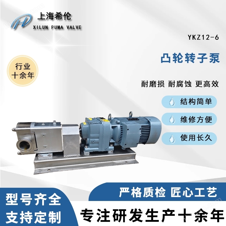
The 50QY-12 5.5kw stainless steel gas-liquid mixing pump is suitable for liquid transportation, gas-liquid mixing and stirring, circulation, and pressurization. Typical applications: Air flotation treatment equipment, odorous water production equipment, and various temperature control devices for the circulation and transfer of heat and refrigerant in preparation and chemical equipment; Various filtering devices;
Product Details
50QY-125.5kw stainless steel gas-liquid mixing pump
50QY-125.5kw stainless steel gas-liquid mixing pump


Operating conditions
·Thin, clean, low viscosity liquid; ·The pH range is 3-9; Liquid temperature: -15C~+120C; ·Environmental temperature:+40C; gas-liquid volume ratio of approximately 1:9 (suction volume of 8-10%); The self-priming height is 9-NPSH (m).
Operation steps: i) Before the initial operation, the pump must be filled with water, and then the inlet and outlet valves must be fully opened. After closing the inlet valve and outlet pressure gauge, briefly connect the power to the pump, confirm that the rotation direction of the pump is correct, and then enter formal operation. Before connecting the power supply during normal operation, be sure to close the intake valve (when manually controlled).
2) Gradually reduce the inlet control valve until the negative pressure on the vacuum gauge shows -100mm Hg+0.3kgf/cm2, then open the suction valve. Open the check valve of the outlet pressure gauge and adjust the control valve of the outlet pipeline until the set outlet pressure is reached.
3) Fine tune the inlet pipeline control valve, suction valve, and outlet pipeline control valve until the liquid flow rate, gas flow rate, and outlet pressure reach the predetermined values. The gas injection amount is about 7-8% of the water injection amount, with a maximum of no more than 10%. Example: When the water injection rate is 30/min, the gas injection rate is 2.4~3.0/in;
When the water injection rate is 501/min, the gas injection rate is 4.0~5.0 l/min.
4) After the water flow rate, intake volume, and outlet pressure reach the set values, normal operation can be achieved. 5) When stopping the operation of the pump, the suction valve must be closed first, and then the pump must be turned off. 2. Precautions;
1) As the suction volume of the pump increases, the discharge flow rate and pressure will gradually decrease. When the suction volume exceeds a certain limit, the pump will experience flow interruption, that is, it will lose its function.
2) When selecting a gas-liquid mixing pump, please refer to the pump's performance curve chart. The discharge pressure of the pump is set according to its purpose. For ozone water mixing, it is generally set at 2-3kgf/cm2, while for dissolved air flotation and oxygenation treatment, it is generally set at 3.5-4kgf/c. When the gas injection ratio is 7-8%, please choose a pump with a flow rate greater than the actual discharge flow rate.
3) The outlet pressure required to generate microbubbles usually does not exceed 4kgf/crm2, and a pressure exceeding 4kgf/cm? There is no significant change in the diameter of the bubbles and the amount of dissolved gas, but it will only reduce the amount of dissolved gas and increase the power consumption of the pump.
4) Setting of gas injection volume:
The solubility of gas in water is generally 3% of the water flow rate (saturated solubility at normal pressure). The gas injection rate of the gas-liquid mixing pump should be greater than the saturated solubility, and it is recommended to set it at 7-8% of the water flow rate, with a maximum of 10%. In addition, the undissolved part of the gas injected into the pump flows in the form of large bubbles in the pipeline, which may form gas pockets at the pressure relief valve and affect the occurrence of microbubbles. Therefore, it is recommended to install a gas-liquid separation tank before the pressure relief valve to discharge excess gas. gas-liquid
The size of the separation tank is generally set according to the flow rate of the pump, but for convenience, it is set according to the diameter of the pump's drainage port as follows:
Pump drainage diameter
~32mm
40 mm
50 mm
Gas liquid separation auxiliary capacity
4 liters
8 liters
29
5) To ensure the suction effect, a gas suction nozzle is generally used at the suction port of the pump. The nozzle guides gas into the vicinity of the impeller and smoothly introduces gas and liquid into the pump's flow channel with the help of the impeller's rotational force. The use of gas nozzles can ensure stable inhalation and efficient dissolution of gases. It is recommended to equip the gas nozzle with a one-way check valve to prevent the reverse overflow of liquid. The combination of one-way check valve and solenoid valve can basically avoid the reverse overflow of liquid. If the gas-liquid mixing device is manually controlled, one-way check valves and solenoid valves can be omitted, but the operating procedures should refer to the operating instructions.
6) To ensure the generation of good microbubbles, the discharge pipeline behind the pressure relief valve should be designed with the following precautions:
A. The diameter of the drainage pipeline should be the same or larger than the outlet diameter of the pump;
B. The top outlet of the drainage pipeline should be set horizontally or upwards, and cannot be set downwards
C. When releasing microbubbles, the pore diameter should not be less than 10mm;
D. The length of the drainage pipeline before the outlet valve is generally set to 0.5-1m, and the pipeline after the outlet valve should be as short as possible;
B. Gas flow meters are used to adjust and control the amount of gas inhaled. The material of gas suction nozzles and gas flow meters is generally determined by the medium of the inhaled gas and liquid, and stainless steel is required for use in ozone equipment.
7) Inhalation route
A. The diameter of the suction pipe is generally the same as or larger than the suction diameter of the pump. B. When using negative pressure to suck in gas, the diameter of the suction pipe sometimes needs to be one level smaller, but not too small;
C. When the liquid level of the water supply tank is lower than the center height of the pump, a bottom valve should be installed at the lowest end of the suction pipe;
D. The suction pipeline should be equipped with a filter screen (60 days) to remove solid substances from the liquid.