The liquid nitrogen subcooling cycle system equipment (SLNCS) is a core peripheral device designed specifically for low-temperature permanent magnet wigglers (CPMU). As a key component of the third-generation synchrotron radiation source, CPMU needs to work in the liquid nitrogen temperature range (about 82K) to enhance the magnetic field peak (30%~50% higher than that of a vacuum oscillator) and coercivity (more than 50% higher), thereby obtaining higher brightness X-ray synchrotron radiation. SLNCS ensures efficient operation of CPMU by providing a stable supercooled liquid nitrogen cold source

SLNCS meets the stringent requirements of CPMU and has the following key performance features:
temperature controlThe working temperature of the subcooled liquid nitrogen outlet is 78-80K, with a temperature control accuracy of ± 0.2K and an inlet and outlet temperature difference of ≤ 3K, ensuring stable temperature of the CPMU magnet.
flow regulationThe working volume flow rate is 9.7L/min, with an adjustable range of 2.0~19.4L/min. It can be flexibly adapted to different thermal load requirements through a liquid nitrogen pump frequency converter.
pressure controlThe working pressure is 0.3MPa (gauge pressure), the adjustment range is 0.15~0.5MPa, and the pressure fluctuation is ≤± 7.5kPa, ensuring the stability of liquid nitrogen single-phase supercooling state.
cooling capacityThe maximum available cooling capacity is 1300W, which can meet the heat dissipation needs of CPMU under high loads.

Liquid nitrogen subcooling circulation system equipment

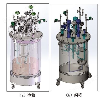
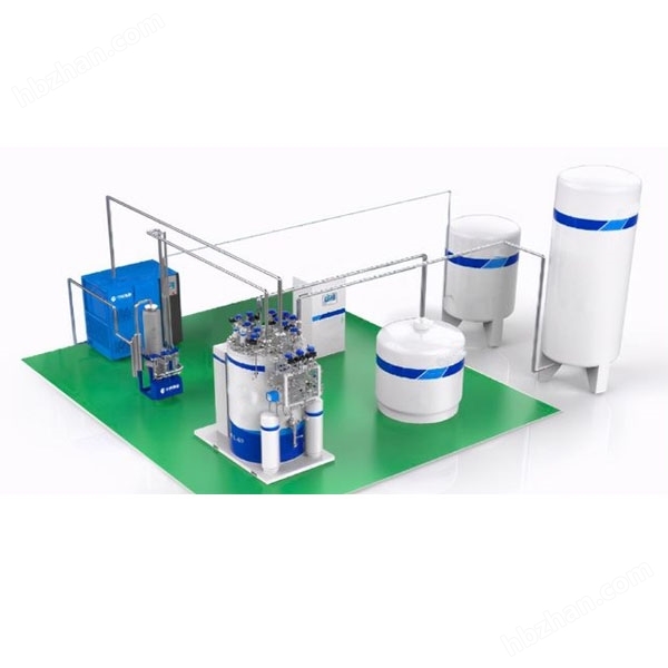
SLNCS uses atmospheric liquid nitrogen (77.36K) as the cold source, mainly composed ofLow temperature cold box、valve boxandVacuum insulated pipelinecomposition
Low temperature cold boxThe system core integrates cold supply and circulation power components, including cold box Dewar, liquid nitrogen pump, subcooling heat exchanger, automatic pressure control device, etc.
valve boxResponsible for flow regulation and backup functions, controlling liquid nitrogen distribution through low-temperature valves, and switching to backup liquid nitrogen source in case of cold box failure to ensure continuous operation of CPMU.
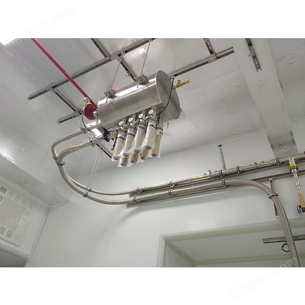
Vacuum insulated pipelineConnect the cold box, valve box, and CPMU to reduce cooling loss and ensure low-temperature transmission efficiency.
The subcooled liquid nitrogen flowing out of CPMU enters the cold box through a vacuum pipeline and is pressurized by a liquid nitrogen pump;
The pressurized liquid nitrogen enters the subcooling heat exchanger and exchanges heat with the atmospheric liquid nitrogen inside the cold box, restoring the subcooled state (78-80K);
After being regulated by the valve box, supercooled liquid nitrogen flows into CPMU to absorb heat from the magnet;
After absorbing heat, the liquid nitrogen returns to the cold box to complete the cycle.

The cold box is the core of the liquid nitrogen circulation system, and all important components are integrated into the cold box. The function of the valve box is to distribute the supercooled liquid nitrogen provided by the cold box, and adjust the amount of supercooled liquid nitrogen supplied to CPMU to an appropriate value by opening and closing various low-temperature valves in the valve box; At the same time, the valve box can provide atmospheric pressure liquid nitrogen and gas-liquid phase separation for CPMU in case of cold box failure, ensuring that the single-phase flow entering the circulation is for temporary low-temperature operation of CPMU.
The cold box consists of a cold box Dewar and an upper cover plate assembly. The upper cover plate assembly consists of an upper cover plate, a subcooled heat exchanger, a liquid nitrogen pump, an automatic pressure control device, a control valve, a pressure and temperature measurement sensor, and other safety components. The valve box is mainly composed of a vacuum container, a low-temperature pneumatic valve, a manual low-temperature valve, connecting pipelines, and other safety measurement components. The three-dimensional design of the cold box and valve box is shown in Figure 4. 3.1 Cold box Dewar
The cold box Dewar is a vacuum insulated wide mouth Dewar structure, which holds a certain amount of atmospheric liquid nitrogen inside the Dewar and provides cooling to the system through the evaporation of atmospheric liquid nitrogen. The design working pressure of the inner cylinder is 0.25 MPa, the material is SUS304, the size is φ 850 mm, the thickness is 2 mm, and the bottom is a head structure. The interlayer is vacuum, and the outer cylinder is subjected to an external pressure of 0.1 MPa. The material is SUS304, and after design calculation and ANSYS simulation, the size is φ 950 mm, the thickness is 4 mm, and the bottom is a head structure.
functionStore atmospheric liquid nitrogen to provide a cold source for the subcooling heat exchanger.
The automatic pressure control device is the core component of the liquid nitrogen circulation system, where the circulation pressure of the entire circulation system is generated and controlled to keep the circulating liquid nitrogen in a supercooled state of single-phase flow. The automatic pressure control device includes a pressure control container, a replenishment valve and a release valve, a heating device, pressure measurement and control, a pressure pipeline, and safety components. A certain pressure should be maintained in the automatic pressure control device. The pressure must be much higher than the saturated vapor pressure of the refluxed liquid nitrogen to ensure that the refluxed liquid nitrogen is supercooled without the generation of bubbles. The automatic pressure control device is equipped with a heater, which maintains a high pressure in the automatic pressure control device by heating the liquid nitrogen in the container. The automatic pressure control device is connected to the circulation system through a pipeline, transmitting pressure to the circulation system. The pressure is 0.15~0.5 MPa (gauge pressure), corresponding to a saturation temperature of 86~96K. The normal working pressure is 0.3 MPa (gauge pressure).
During the circulation process, due to certain system leaks, the liquid nitrogen in the circulation system will gradually decrease. When the liquid nitrogen in the automatic pressure control device decreases to the set value (monitored by the liquid level meter), it prompts the liquid nitrogen storage tank to replenish liquid nitrogen into the automatic pressure control device. The design working pressure of the pressure control vessel is 0.15~0.5 MPa, the commonly used working pressure is 0.3 MPa, and the design pressure resistance is 1.0 MPa. The material is SUS304 and the capacity is 18 L.
composeIncludes an 18L pressure control vessel (made of SUS304 material, with a pressure resistance of 1.0MPa), a fluid replenishment/release valve, a heating device, and a pressure sensor.
principleMaintain a pressure of 0.15-0.5MPa (commonly 0.3MPa) by heating the liquid nitrogen inside the container to ensure that the circulating liquid nitrogen is in a single-phase supercooled state; When the liquid level is below the set value, it will automatically replenish to ensure system stability.
selectionAdopting the BNCP-30G000 centrifugal pump from Barber Nichols Inc in the United States, adapted with a frequency converter to regulate the flow rate.
performanceThe maximum flow rate is 33L/min, the maximum head is 43m, and the liquid nitrogen column can overcome the total resistance of the system at 63kPa (along the way resistance of 49kPa+local resistance of 14kPa), meeting the requirements of flow regulation.
Material and StructureA spiral coil is made of copper tube (φ 25 × 2), with a length of 27.6m (including 1.3 times the margin), a spiral diameter of 800mm, and a total of 11 turns.
performanceThe heat exchange area is 1.429m ², and the high-pressure liquid nitrogen inside the tube efficiently exchanges heat with the atmospheric pressure liquid nitrogen outside the tube. The inlet temperature is 83K and the outlet temperature is 80K, meeting the requirement of 3K heat exchange temperature difference.
The system has been verified through offline and online testing, and its performance fully meets the standards
Pressure stability24-hour pressure fluctuation ≤ 2kPa (good when the liquid level of the pressure control container is 30%~40%), offline testing pressure fluctuation is only 1.825kPa.
Temperature and flow rateThe temperature difference between import and export is less than 3K, the temperature control accuracy is ± 0.2K, and the flow regulation range covers 2.0~19.4L/min.
Fault redundancyThe backup system can seamlessly switch in case of cold box failure, ensuring uninterrupted operation of CPMU.
SLNCS not only meets the cooling requirements of low-temperature permanent magnet wigglers (CPMUs), but its high-precision temperature and pressure control capabilities are also applicable to monochromators and other equipment of synchrotron radiation sources, laying the foundation for domestic technological breakthroughs in related fields. It is a key supporting equipment for international research and application of synchrotron radiation sources.