The integrated manufacturer of 24 cubic welded fire box pump integrates 24m #179; The welded stainless steel water tank (approximately 24 tons of water) is an integrated fire pressure boosting and stabilizing equipment with fire pump units, stabilizing systems, and intelligent control systems. It provides initial water supply and stable water pressure for building fire protection systems, meeting the needs of fire hydrants and automatic sprinkler systems.
24 cubic welded fire box pump integrationIt is a fire pressure boosting and stabilizing equipment that integrates a 24m ³ (approximately 24 tons of water) welded stainless steel water tank with a fire pump unit, a stabilizing system, and an intelligent control system. It provides initial water supply and stable water pressure for building fire protection systems, meeting the needs of fire hydrants and automatic sprinkler systems.
Core parameters:
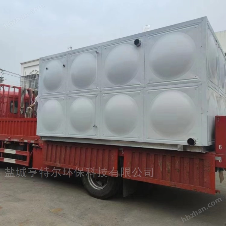
Water tank capacity: 24m ³ (24 tons), meeting the initial fire water demand
standard size4m x 3m x 2m (length x width x height), covering an area of approximately 12 square meters, with flexible and adjustable height
material304/316L food grade stainless steel (thickness: bottom plate ≥ 2.5mm, side wall decreasing by 1.5-2.0mm)
design pressure:0.5-1.2MPa, Meet the requirements of different building heights
Applicable trafficFire hydrant system ≥ 20L/s, sprinkler system ≥ 10L/s
Head range30-120m (calculated based on building height+pipeline loss)
Operating Temperature5-40 ℃, suitable for conventional building environments


Material Selection:
structural characteristics:
Fully welded integral molding, no bolt connection gaps, sealing performance
Internally equipped with galvanized/stainless steel reinforcement support (spacing ≤ 1m) to enhance compressive strength
Curved bottom plate design, no dead corners due to water accumulation, easy to clean and maintain
The top plate is fully welded (I-type weld), and the side walls and bottom plate are welded with V-shaped welds to ensure strength
Key points of welding process:
adoptargon arc weldingProcess (non ordinary welding) to avoid carbon steel pollution and ensure the corrosion resistance of stainless steel
Welding material: ER308/ER316L stainless steel welding wire, matched with the water tank material
Weld seam requirements: full and uniform, without porosity, slag inclusion, virtual welding, and smooth surface
The supporting structure mustfull welding(Spot welding is strictly prohibited) to ensure strength
Weld seam inspection: Full water test (observing water level drop of ≤ 2mm after 48 hours) and 0.2MPa pressure test (holding pressure for 30 minutes without leakage)

Typical configuration:
Characteristics of water pump:
adoptXBD type fire special pump(Compliant with GB 6245-2019 standard), ensuring stable performance
Dry motor design (non submersible pump), good heat dissipation, long service life, easy maintenance
Pump casing: cast iron/stainless steel, impeller: bronze/stainless steel, shaft seal: mechanical seal
core component:
PLC control cabinet (IP65/68 protection): built-in fire protection program, real-time monitoring and control
Touch screen human-machine interface: displays pressure, water level, pump status, supports local operation
Sensor group: pressure (accuracy ± 0.02MPa), water level (accuracy ± 10mm), temperature, current sensors
Remote monitoring module (optional): 4G/5G communication, supports mobile APP/PC monitoring and alarm
core functionality:
Automatic voltage stabilizationMaintain the pressure of the pipeline network at the set value (such as 0.8MPa ± 0.02MPa)
water level controlLow water level alarm and pump shutdown (to prevent dry burning), high water level overflow protection
Intelligent rotation of pump unitsBalance the running time of each pump and extend the overall lifespan
Multi level pressure controlAutomatically adjust the number of running pumps according to water consumption, energy-saving and efficient
Fault self diagnosisIdentify and display the fault location, trigger the sound and light alarm, and upload it
fire alarm linkageCan be connected to the automatic fire alarm system, and immediately start the main pump upon receiving a fire alarm signal
The stabilizing pump continues to operate, maintaining the pipeline pressure at the set value (such as 0.8MPa)
The pressure tank stores about 300L of emergency water. When there is a slight leakage in the system, it is replenished by the pressure tank to reduce the frequency of starting the stabilizing pump
The water tank is automatically replenished with water through a float valve/solenoid valve to maintain the water level within the normal range (60% -90% volume)
Fire occurs → Fire hydrant/sprinkler outlet → Pipe network pressure drops →
The pressure sensor detects that the pressure is below the start-up threshold (such as 0.7MPa)
The PLC controller immediately starts one fire hydrant main pump/sprinkler main pump
If the pressure continues to decrease (water consumption increases), the backup pump (multiple pumps in parallel) will be automatically started to provide the design flow rate and pressure
The water tank continues to supply water and the water level is monitored in real time. When it drops to the low water level warning line (about 10% of the volume), the pump unit will stop running to prevent dry burning
The system remains running until the fire signal is released or manually reset
Pump unit malfunctionWhen the running pump experiences overload/short circuit/mechanical failure, the system automatically switches to the backup pump and alarms
overvoltage protectionWhen the pressure in the pipeline exceeds 1.15 times the design value, the safety valve automatically opens to release pressure
power failure protectionOptional EPS emergency power supply, maintain control system operation for ≥ 30 minutes after power failure to ensure emergency operation
WHDXBFCode for integrated pump station of intelligent box pump with fire pressure stabilization
24Effective volume of water tank (24m ³)
36/18The flow rate of the fire main pump is 36m ³/h, and the flow rate of the sprinkler main pump is 18m ³/h
60Pump head (60m)
IIConfiguration level (two in use and one backup, or dual-purpose configuration)
Foundation Construction:
Pouring C30 concrete foundation (thickness ≥ 250mm), flatness error ≤ 5mm
Pre embedded anchor bolts, with spacing matching the equipment base
Set up drainage ditches around the foundation to ensure smooth drainage
Equipment in place:
Whole lifting (pay attention to the position of the lifting point), place it on the foundation and level it (levelness ≤ 1 ‰)
Tighten the anchor bolts to ensure stability
pipeline connection:
Connect the inlet, outlet, and outlet pipelines (recommended stainless steel/hot-dip galvanized steel pipes)
Seal the pipeline connection to prevent leakage
Supporting pipeline systems to reduce stress on equipment interfaces
Electrical installation:
Connect the power supply of the control cabinet (three-phase five wire 380V/50Hz) and ensure proper grounding (grounding resistance ≤ 4 Ω)
Connect sensors and pump control lines, and do a good job of waterproofing treatment
Test insulation performance to ensure safety
system debugging:
Check the correct installation of each component and manually test the operation of the pump unit
Simulate daily voltage stabilization, fire start-up, fault switching and other working conditions
Calibrate pressure/water level sensors, set control parameters
Test remote monitoring and alarm functions