-
E-mail
1743251064@qq.com
-
Phone
13403270026
-
Address
Botou Development Zone, Hebei Province
Product Categories
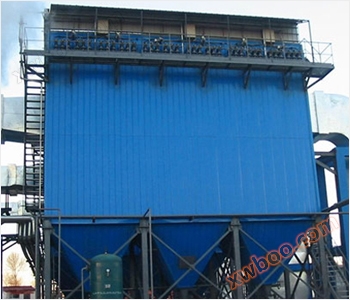
- Pulse dust collector
- Star shaped unloader
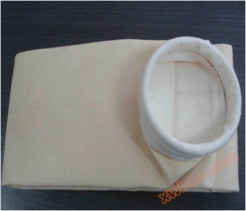
- Dust bag
- Spiral conveyor
- Cyclone dust collector
- Dust humidifier
- Dust removal framework
- Low temperature plasma exhaust gas treatment equipment
- precipitator
- Dust removal accessories
- Single dust collector
- Boiler dust collector
- bag-type dust collector
- Plasma oxygen integrated machine
- Catalytic combustion equipment
- Industry dust collector
- Welding smoke purification equipment
- other
- UV photo oxygen exhaust gas treatment equipment
Botou Longnuo Environmental Protection Equipment Co., Ltd

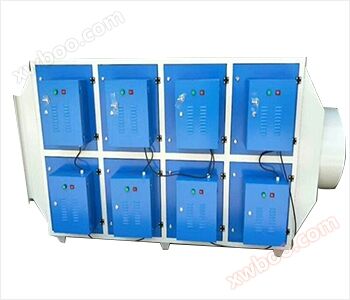
RCO catalytic combustion equipment
NegotiableUpdate on 08/02
- Model
- Nature of the Manufacturer
- Producers
- Product Category
- Place of Origin
Overview
Introduction to RCO catalytic combustion equipment: RCO catalytic combustion equipment refers to a device or equipment that burns under the action of a catalyst The working principle of catalytic combustion equipment is to use a catalyst to conduct flameless combustion of organic waste gas at a lower ignition temperature, decomposing the organic waste gas into carbon dioxide and water vapor
Product Details


RCO catalytic combustion equipment refers to a device or equipment that burns under the action of a catalyst. The working principle of catalytic combustion equipment is to use a catalyst to conduct flameless combustion of organic waste gas at a lower ignition temperature, decomposing the organic waste gas into carbon dioxide and water vapor. The electrical control system of catalytic combustion equipment consists of PLC controller, text display, frequency converter, igniter, ultraviolet sensor, thermocouple and other electronic control equipment, as well as a fan. In addition, the ratio of gas to air is regulated by a zero pressure valve.
Combustible materials burn under the action of catalysts. Compared with direct combustion, catalytic combustion has a lower temperature and more complete combustion. The catalyst used for catalytic combustion is a multi-component substance consisting of precious metals and metal oxides with a large specific surface area. For example, catalytic gas stoves loaded with Pd or rare earth compounds for household use can reduce the CO content in exhaust gas and improve thermal efficiency. The alumina catalyst loaded with 0.2% Pt can burn and deodorize most organic compounds to a chemical shift of σ=1 or below at 500 ℃. Catalytic combustion is flameless combustion, making it suitable for high-performance applications such as fuel cells using H2 and O2 as raw materials, and pocket furnaces using gasoline or alcohol as raw materials (with Pt impregnated asbestos as catalyst). To eliminate the smoke of NOx in chemical plants, fuel can be added to the smoke and catalytic combustion can be carried out using supported platinum and palladium catalysts to convert NOx into N2 gas. The combustion method involves using appropriate catalysts to decompose and oxidize combustible substances in harmful gases at lower temperatures.
The electrical control system of RCO catalytic combustion equipment consists of PLC controller, text display, frequency converter, igniter, ultraviolet sensor, thermocouple and other electronic control equipment, as well as a fan. In addition, the ratio of gas to air is regulated by a zero pressure valve. The working process of the catalytic combustion electrical control system is divided into three states: burner working state, stop state, and parameter setting state. In the working state, it is divided into ignition process and combustion process. The temperature is detected by the installed thermocouple and displayed on a text monitor. PLC has analog input and output modules, which detect flame combustion signals and thermocouple temperature signals. After comparing and calculating the detected signals with the set signals, the output frequency of the frequency converter is controlled by a 0-10V electrical signal to adjust the fan speed and maintain the combustion temperature of the burner. This constitutes a control system based on the set temperature; Automatically detect the temperature signal of the burner and compare it with the set temperature, output various alarm signals or directly shut down. The monitor can display gas flow rate, combustion temperature, and output frequency of the frequency converter. Set parameters and work status information; The operating temperature parameters can be adjusted online through the display, and the set temperature can be modified to control the operation of the fan. The system also has multiple protection functions, especially strong logic interlock function, to ensure reliable system operation and has relatively complete control functions.